Well, I've measured plenty of triodes under CCS loading, and then in half-mu form under similar Va/Ia conditions, and found the THD of the latter to be far higher than the former. But perhaps I'm being naive in my expectations.Anyway, have we established that it "ain't"? Has someone calculated/measured the variation of mu with anode voltage/current and shown that this does not explain the measured nonlinearity?
Is the expected benefit seen in simulation? If so, that suggests that the theory is correct. If not seen in practice then the most likely explanation is poor triode matching.
Note that theory tells us that CCS loading gives good results given constant mu (in one triode). Theory also tells us that half-mu gives good results given constant mu and excellent matching of two triodes - hence theory tells us that the CCS version should be better in practice and equal in simulation. If that is what is seen then the theory is correct, but perhaps often misunderstood and misapplied?
Note that theory tells us that CCS loading gives good results given constant mu (in one triode). Theory also tells us that half-mu gives good results given constant mu and excellent matching of two triodes - hence theory tells us that the CCS version should be better in practice and equal in simulation. If that is what is seen then the theory is correct, but perhaps often misunderstood and misapplied?
Back to the theory
Hello All,
Either you all get up early or you are time zones ahead of me.
I suspect that poorly matched triodes is not the issue, perhaps to a degree however not more than a few percent, not db’s. We will see.
Back to the theory:
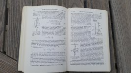
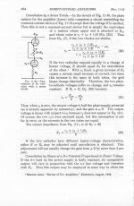
The first place I recall seeing the theory is from the 1940’s in the MIT Radiation series #18 “Vacuum Tube Amplifiers”. See the attached photo of page #464. They go through a lot of math and show rp is equal in both the top and bottom triode. This is true for idle conditions.
This is me scratching my head; as a signal is applied to the bottom triode control grid the voltage on the top triode grid is going the other direction. As we slide up and down the plate curves of the pair of triodes the instantaneous rp’s of the triodes are moving in opposite directions and not canceling out as is assumed and shown in equation (91) on page 464.
Hats off to SY. If the applied B+ voltage is increased we are operating at a part of the plate curve where the change in rp is not so steep and perhaps we do see some distortion cancellation.
DT
Hello All,
Either you all get up early or you are time zones ahead of me.
I suspect that poorly matched triodes is not the issue, perhaps to a degree however not more than a few percent, not db’s. We will see.
Back to the theory:
The first place I recall seeing the theory is from the 1940’s in the MIT Radiation series #18 “Vacuum Tube Amplifiers”. See the attached photo of page #464. They go through a lot of math and show rp is equal in both the top and bottom triode. This is true for idle conditions.
This is me scratching my head; as a signal is applied to the bottom triode control grid the voltage on the top triode grid is going the other direction. As we slide up and down the plate curves of the pair of triodes the instantaneous rp’s of the triodes are moving in opposite directions and not canceling out as is assumed and shown in equation (91) on page 464.
Hats off to SY. If the applied B+ voltage is increased we are operating at a part of the plate curve where the change in rp is not so steep and perhaps we do see some distortion cancellation.
DT
For an ideal triode (3/2 law, constant mu) rp (ra to us Brits) is a function of current only. In that case the half-mu stage with an infinite impedance load should give distortion cancellation, as the two triodes will have the same current so same rp. To the extent that real triodes depart from the ideal law they will have degraded distortion cancellation. Whether a CCS stage or a half-mu stage will win depends on exactly how mu varies, as both give perfect results for an ideal triode.
Many real triodes can be biased so mu is almost independent of current, over a limited range. What we actually want is mu almost independent of anode voltage. I don't know if any datasheet gives the curves for that.
I guess the book assumes ideal triodes.
Many real triodes can be biased so mu is almost independent of current, over a limited range. What we actually want is mu almost independent of anode voltage. I don't know if any datasheet gives the curves for that.
I guess the book assumes ideal triodes.
Last edited:
Here is a closer scan of the MIT book, page 464.
(these reprint books are falling apart now)
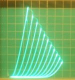
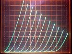
Then a typical triode curve set pic.
Every triode curve set I've seen has a roll-over effect at high plate voltage. (so higher Rp at higher Vp) Just a matter of how much between different tubes. Likely a grid "island effect", from grid wire proximity to the cathode. The Aikodo stage is probably popular because it preserves some 2nd Harmonic distortion from the plate voltage effects.
One can get an anti island effect by using grid 2 for input in an aligned grid tube. (grid 1 connected to cathode)
But then the "triode" Rp is way too high.
(these reprint books are falling apart now)
Then a typical triode curve set pic.
Every triode curve set I've seen has a roll-over effect at high plate voltage. (so higher Rp at higher Vp) Just a matter of how much between different tubes. Likely a grid "island effect", from grid wire proximity to the cathode. The Aikodo stage is probably popular because it preserves some 2nd Harmonic distortion from the plate voltage effects.
One can get an anti island effect by using grid 2 for input in an aligned grid tube. (grid 1 connected to cathode)
But then the "triode" Rp is way too high.
Attachments
Last edited:
True, the current changes in the Aikido circuit versus signal. But the theory (for 3/2 power law) says the top and bottom Rp vary the same way with current, so that should null out. So all should be well. (does a simulation with 3/2 law tube models show constant gain?)
The variation of Rp with plate voltage (at constant current even) is definitely an issue though.
Anyone tried putting a CCS tail under a doubled up (differential) Aikido stage?
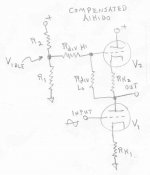
Another idea:
With the simple Aikido stage, put a high value resistor from the top grid to some fixed (idle) voltage. And a low value resistor from the top grid to the top tube cathode (as usual). That resistor could be adjusted so as to compensate the top tube for the varying Rp with voltage. (as the center point of the Aikido gets pulled down, the top tube would draw a little extra current)
The variation of Rp with plate voltage (at constant current even) is definitely an issue though.
Anyone tried putting a CCS tail under a doubled up (differential) Aikido stage?
Another idea:
With the simple Aikido stage, put a high value resistor from the top grid to some fixed (idle) voltage. And a low value resistor from the top grid to the top tube cathode (as usual). That resistor could be adjusted so as to compensate the top tube for the varying Rp with voltage. (as the center point of the Aikido gets pulled down, the top tube would draw a little extra current)
Last edited:
Ran out of time for editing on the last idea. Should be:
Another idea:
With the simple Aikido stage, put a high value resistor from the top grid to some fixed (idle) voltage. And a low value resistor from the top grid to the bottom tube plate (as usual). The high value resistor could be adjusted so as to compensate the top tube for the varying Rp with voltage. (as the center point of the Aikido gets pulled down, the top tube would draw a little extra current)
Attachments
Last edited:
Constant current is not needed; just equal currents, which is what you have with an infinite load. And ideal triodes!DualTriode said:Even with an “ideal” 3/2 exp rule triode the half mu amplifier is not constant current. Even with constant mu, mu = gm * rp. Change the grid voltage and the current changes with gm and rp going in opposite directions.
Anyone tried putting a CCS tail under a doubled up (differential) Aikido stage?
nib cause we are lazy drinking an chatting in the forum

who has a transistor in his part box? *runs
Ya, bottom line aikido is a 2dn harmonics machine, it appeals to the tubby sound crew
This is a fascinating discussion and why more enthusiasts should poke around diyaudio.com.
Most of what I can follow seems to be focused on the input tube for the Aikido arrangement. Ignoring that for the moment, the aspect that interests me most is the way power supply noise is injected into the output tube. Are there any thoughts on this?
It seems as though it would be really useful in higher gain circuits where brute force power supplies are impractical (eg 1U microphone preamps). In this application, preserving some of the harmonics (ie "tone") wouldn't necessarily be frowned upon if the claims about linearity don't hold true, but PSR would be a big feature.
Cheers and salud to you tube nerds.
It does provide some noise cancellation, but you really have to trim it to hit the null.
That makes sense. The approximation that JB provides for the appropriate voltage divider is pretty loose.
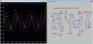
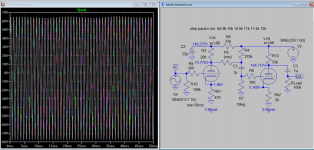
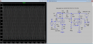
Here is a simulation based on JB article A New Look at Harmonic Restoration
The supply is modulated with 1V 60hz to simulate the hum.There are some phase shift just before and after null occurred. Do you see the 60hz hum still on top? That is because the top has entered clipping, more clipping more hums.
The supply is modulated with 1V 60hz to simulate the hum.There are some phase shift just before and after null occurred. Do you see the 60hz hum still on top? That is because the top has entered clipping, more clipping more hums.
Attachments
Last edited:
Constant current is not needed; just equal currents, which is what you have with an infinite load. And ideal triodes!
Dr Dave,
You are a smart guy and a clear thinker. I admit that I am hard headed and abrupt. Plus we are speaking about a perfect 3/2 law triode that does not exist however it is important for me to understand the ideal model.
If we had a set of curves for this ideal triode we could draw a sketch of what we are speaking of and come to an agreement as to what is going on in this Half mu thing.
My first premise is if we draw a constant current line across this set of triode curves the slope of each curve decreases as the grid voltage is more negative as we move across the curves going from left to right. This is true for any equal current line that we draw. Or is this not true?
I am just back from a trip to the woods with my wife.
I am going to put the mental image of the ideal 3/2 law triode under my pillow and sleep on it.
DT
For an ideal triode each Va-Ia curve is exactly the same shape, just displaced sideways by voltage 'mu x Vg'. Hence a horizontal (constant current) line sees the same slope everywhere.DualTriode said:My first premise is if we draw a constant current line across this set of triode curves the slope of each curve decreases as the grid voltage is more negative as we move across the curves going from left to right. This is true for any equal current line that we draw. Or is this not true?
Often in the real world we can gain insight from thinking about the ideal case. It may be that for the half-mu stage real triodes are sufficiently different from ideal triodes that the ideal case has led us astray. The problem is that people like me who do maths like ideal cases, while the rest of the world likes a simple statement "top and bottom triode distortions cancel as it is push-pull"; both perhaps wrong?
I should also mention that I built an Aikido Cathode Follower recently with a simple CRC (220uf - 1.2k - 220uf, IIRC) and it turned out completely silent. That's just the 'output' stage of the Aikido topology and so it does include the claimed inverse noise injection dealio.
No idea whether a regular cathode follower would have been as hum free with the same power supply.
No idea whether a regular cathode follower would have been as hum free with the same power supply.
- Home
- Amplifiers
- Tubes / Valves
- Survey: Aikido distortion