DreadPirate said:I'm looking at adding volume control and upsizing the input caps. I found this diagram for the SI amp. For this unit, do I remove C13 and C21, jumper them, then follow this diagram? Do the existing input caps need to removed at all, or can I just jumper across them?
I do not have shielded cable for the RCA run. Will twisting the two wires from the jack be good enough? I will not be running near the power cables at all.
I'm also going to tack on at least one 220uF low esr cap I have lying around onto the existing 100uF SMDs for a 520uF value per side, is this worth the trouble? Bass is actually pretty decent with the existing 3x100uF...
Hi, changing C13 & C21 will improve the bass. It is easier to remove and bridge them, then add your caps of choice before the CH1 & CH2 inputs..
Just twisting the input cables should be OK..
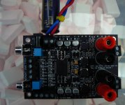
I just added an extra tank cap at the PS input for now.
I added my 2.2uf input caps on the board..
Attachments

DreadPirate said:Would a 10K attenuator work, or do I need something a bit higher? Are all ALPS pots pinned the same? I have this little mini-pot I'd like to use...
If it is a 6 pins pot it is ok.
I can't seem to touch these t-amps w/o destroying them. I probably did several things while attempting to mount onto another board w/ hardmounted rca inputs and screw terminal outputs (this board fits into a nice brushed aluminum case, was trying to piggy-back this board and use its connectors, bad idea, most of the connectors were shorted to each other for some reason).
I know I did at least two things wrong. I reversed the polarity on the inputs and probably shorted the + and - leads on the outputs. I'm now getting 4.5VDC at idle on one of the channels. Amazingly, the other channel's offset is still at its original reading of 500mV or so. I'm reading 2V or so at the input terminals. So, is there any obvious culprits here or do I spring for another board?
I know I did at least two things wrong. I reversed the polarity on the inputs and probably shorted the + and - leads on the outputs. I'm now getting 4.5VDC at idle on one of the channels. Amazingly, the other channel's offset is still at its original reading of 500mV or so. I'm reading 2V or so at the input terminals. So, is there any obvious culprits here or do I spring for another board?
GuyPanico said:Is it possible to control two amplifiers with a single volume knob?
Yes!

Obviously, you need a strong source when splitting the signal... and you will have to use more volume but there is no reason why not.
Dreadpirate:
Could be a number of things but at this price you may as well get a new one

According to the spec sheet for the TA2024, the overcurrent protection might need to be reset? The output voltage I'm seeing (on one channel only) is about 1/2Vdd. Should I jumper MUTE and FAULT? The 4.5VDC problem was intermittent at first and now seems to hold all the time. Powering down does not cause it to reset, though, and it sounds like it should.
Yes, another one is on order...
http://www.tripath.com/downloads/TA2024.pdf
Yes, another one is on order...
http://www.tripath.com/downloads/TA2024.pdf
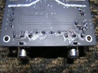
Yikes, found a strand of solder wick shorting C25 to R17, now works fine.
I have a grounding question: My 12V DC jack is not isolated and the outer case is in contact with my AL housing. Is this ok? I found some shielded cable (some two conductor cable used inside computers between the sound card and CD drive), do I ground this shielding to the AL case? The RCA and speaker jacks I know should not be in contact with the housing, not sure about this power jack though.
I have a grounding question: My 12V DC jack is not isolated and the outer case is in contact with my AL housing. Is this ok? I found some shielded cable (some two conductor cable used inside computers between the sound card and CD drive), do I ground this shielding to the AL case? The RCA and speaker jacks I know should not be in contact with the housing, not sure about this power jack though.
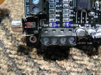
The 4.5VDC on one channel is back. It returned after I reinserted the coupling cap for that channel. After a very careful examination, look what I found on the left input! This little guy is practically invisible against the black background, it's across the input on the channel I was having problems with. It is a 100K resistor. This needs to come off, doesn't it?
I have also noticed that boards shipped after mine (I was one of the first orders board no. A40796), the R17/C23 designation is corrected (reversed on mine) and diodes D2-D5 were added (board no. A41334).
I have also noticed that boards shipped after mine (I was one of the first orders board no. A40796), the R17/C23 designation is corrected (reversed on mine) and diodes D2-D5 were added (board no. A41334).
Attachments
Can someone confirm that the lifted pad location I have shown boxed (C21) requires me to connect the other leg of the input capacitor to the right side of R17 (incorrectly designated C25) as shown? And how do you read the traces on this thing, I can barely make them out? Is there some trick?
Attachments
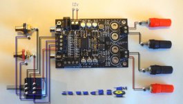
audio1st said:Here is the basic volume control circuit. If you bridge C13 & C21, then add your new caps between the pot and CH1 & CH2 inputs, red and black wires..
this is good stuff...
gychang
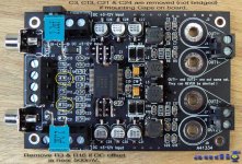
Robert_S said:Having listened to this amp for a few days (and following the advice given, removed C3 & C24)
Robert_S
audio1st said:Here is the basic volume control circuit. If you bridge C13 & C21, then add your new caps between the pot and CH1 & CH2 inputs, red and black wires..
I ordered one and here is the plan on improving with a volume pot.
I will remove C3 & C24, C13 & C21 and jump each, but I am unclear to
A. what are the suggested "new caps" (parts number from digi-key?, can solder SMDs or thru hole parts) and
B. exactly where on the picture should they be soldered onto?
C. any other suggested improvement I have missed?, as u gather I am a newbie with some soldering experience (poor at schematic reading).
thanks,
gychang
Attachments
DreadPirate said:Can someone confirm that the lifted pad location I have shown boxed (C21) requires me to connect the other leg of the input capacitor to the right side of R17 (incorrectly designated C25) as shown? And how do you read the traces on this thing, I can barely make them out? Is there some trick?
Ok, don't want to spread any misinfo here, the trace goes from the lifted location up to R14 right side just adjacent. Someone out there is going to lift these pads...
DreadPirate said:Can someone confirm that the lifted pad location I have shown boxed (C21) requires me to connect the other leg of the input capacitor to the right side of R17 (incorrectly designated C25) as shown? And how do you read the traces on this thing, I can barely make them out? Is there some trick?
Hi DreadPirate, do not connect C21 to R17 with a cap..
What are you trying to do? Have you bridged any caps or are you going to try to mount new input caps on the board.?
C25 and R17 are part of the Sleep cct.
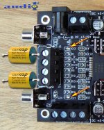
audio1st said:Hi gychang, this is the easiest place to add the 2.2uf input caps after you have bridged C13 & C21. It is the same as with the SI t-amp..
audio1st, your pictures are easiest to follow for the newbie.
gychang
- Status
- This old topic is closed. If you want to reopen this topic, contact a moderator using the "Report Post" button.
- Home
- Amplifiers
- Class D
- Sure Electronics Tripath boards?