What I did with changing PS caps were to remove all the existing ones(ie 6 of them, I don't think they were any good) insert better quality higher capacitance(eg 1000-2000uF) caps on both ends of the board, ie one on each end. It worked fine for me.
Next stage is to change the caps on the 5V regulator.
Next stage is to change the caps on the 5V regulator.
Cheric, Thanks for having a look at my amp. I uploaded some more detail photos as you requested. I added the photos to the other reply, maybe 5 posts back.
Thanks again for your help. Please let me know if you see anything wrong.
Hello nrg2009.
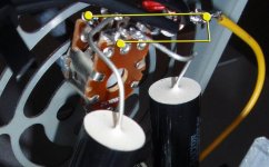
I can't see a ground connection to your pot, the middle terminals connect to the input caps, the end terminals connect to input, (source) and the other end terminals should connect to ground.
Attachments
Last edited:
Audio1st,
You may be right! I used the yellow wire to ground. On the incoming wires I tied the grounds together (L+R), and I connected the yellow wire to the board on the ground of one channel. Is that what hosed me? I should clean up the soldering on the pot and make it more permanent.
Thanks!
You may be right! I used the yellow wire to ground. On the incoming wires I tied the grounds together (L+R), and I connected the yellow wire to the board on the ground of one channel. Is that what hosed me? I should clean up the soldering on the pot and make it more permanent.
Thanks!
Audio1st,
You beat me to it!
Have any ideas on my problem with the power caps ?
Hello cheric, have you measured the voltage at the board with the extra cap, does it drop?
Audio1st,
No, the voltage did not drop at all. I had tried it with 13.8V, 15V, 17.7V power supplies, measured the voltage at each terminals and it was fine.
Only when I added a power cap to any of the terminals (screw-in, power rails and even off board by the power switch). As soon as it powered up with an extra power cap, I would loose channel one (no power at all). Removed the cap and everything was fine again.
I am baffled!
Even tried to remove and bridge D1 and D2 (voltage protection caps, i think), no luck!
Any ideas?
I've replaced my output coils with 10uH coils I bought from board member Arjen Holder.
dr_vega,
I'm still experimenting with winding my cores and it ain't fun.
I want to fit on more windings than a single layer would take.
I can see from the photo of arjen's coils posted on ebay that those coils take to a second layer on the inside of the toroid
http://cgi.ebay.de/ws/eBayISAPI.dll?ViewItem&item=250482866059
It is difficult to discern, however, how exactly the wire is run. Would you be able to describe the knitting pattern of your toroids?
Is the wire run around the toroid in on "general" sense (e.g. clockwise) and with every other winding the wire goes under the previous wire?
Or is the first layer completed first filling the entire inner diameter of the toroid and then a second layer is added going around the toroid once more?
What thickness is the wire on Arjen's cores and what size are the toroids?
Thanks for your assistance
Arjen's toroids are wound single-layer. The core is red which may make it look like there is another layer, but there isn't. It's a tight fit and I had to work the coils tightly together to get 330 degree coverage. They come pretty well filling up the whole 360 degrees.
-dr_vega
What thickness is the wire on Arjen's cores and what size are the toroids?
I'll check the wire and toroid size when I get home this afternoon.
-dr_vega
Been listening a little more to my amp (pics posted a few pages back).I like what I hear, but I can't say I like the, rather bad, turn-on thump I get in my speakers. Is there any way to cure this?
/U.
You can add a timing circuit to either mute the amps or activate relays to disconnect the speakers during turn-on. You should be able to find circuit diagrams pretty easily on the web.
Or you can add a soft-start bypass to the turn-on switch. That's easier and is better for your caps and amps. Again, circuit diagrams are available around the web.
-dr_vega
Arjen's toroids are wound single-layer. The core is red which may make it look like there is another layer, but there isn't. It's a tight fit and I had to work the coils tightly together to get 330 degree coverage. They come pretty well filling up the whole 360 degrees.
-dr_vega
Thanks for the swift response. May I come back though?
Looking at the picture Arjen posted on ebay

I can see that there are windings that pass through the hole and have close contact with the toroid. And there are windings that pass the inside of the core on top of other windings and do not make contact with the inside of the core. This I would call second layer. The question on the knitting pattern is now, do first and second layer alternate while going around the toroid or is there a first layer wound around 360 degrees of the core and then another layer added going around the core a second time.
Even though I am not sure I fully understood you answer, the fact that you are able to free up 30 degree of coverage would mean that first and second layer alternate.
Do your cores resemble the picture at ebay? I have a hard time to believe that with this wire gauge you could press the windings together such that 30 degrees are left open.
Cheers
Do your cores resemble the picture at ebay? I have a hard time to believe that with this wire gauge you could press the windings together such that 30 degrees are left open.
Cheers
My cores are the same as the picture. The last couple of windings are loose and and cross over each other. After I had dressed the windings there were no more crossovers, it is entirely single-layer. I was only able to get a minimun of clear space on the inside of the toroid, almost none. The 30 degrees is on the outside of the toroid. So I guess I don't really have a gap in the windings at all.
-dr_vega
Help!!!
Audio1st,
I received the Meanwell 24V / 6A PS today. When I connected it to the TK2050 board by itself, everything was working fine at the set voltage. But when I added the 2-6800uf power caps to the screw-in terms, the voltage dropped to about 6 volts. Any way to fix this?
Thanks in advance.
/j
Audio1st,
I received the Meanwell 24V / 6A PS today. When I connected it to the TK2050 board by itself, everything was working fine at the set voltage. But when I added the 2-6800uf power caps to the screw-in terms, the voltage dropped to about 6 volts. Any way to fix this?
Thanks in advance.
/j
Nisbeth and Cheric,
both of your issues can be solved with a soft start circuit that slowly fills your caps before the amp comes on.
The SMPS sees a short circuit when a large current flows to fill the caps and goes down in safe mode delivering only ~5V.
Attached you find a sketch of my poor man's version of a soft start circuit.
I use it with the exact Mean Well SMPS and the sure board and it works.
I have roughly 20mF near the amp.
Attachments
- Status
- This old topic is closed. If you want to reopen this topic, contact a moderator using the "Report Post" button.
- Home
- Amplifiers
- Class D
- Sure Electronics New Tripath Board tc2000+tp2050