I indeed considered the SilentSwitcher. Nice toy!
I need 5V, 9V, 12V and 15-18V.
On paper the supereg still looks as the reg with lowest noise and lowest impedance? The supereg also came out best of breed soundwise in linear audio... I'm in doubt about the SS.
I know it's all academic but my CDO(!) disorder always seems to get the last word in discussions with myself...
Can the SilentSwitcher compete soundwise with the supereg?
Yes soundwise certainly. People tell me that often it sound cleaner because of a total absence of any mains-related noise. Depending on the implementation, you can have some main noise or hum etc even when the output of your (super)reg is sqeaky clean. You could say that when you have a perfect implementation, there's no difference in sound quality. If the implementation is not perfect, the SilentSwitcher may have the edge.
The only advantage I see for the superreg is that the output voltage can be easily customized. I'm looking at a SilentSwitcher that can also be user-customized but it isn't so easy while keeping the extremely high performance.
Jan
Great!Yes soundwise certainly. People tell me that often it sound cleaner because of a total absence of any mains-related noise. Depending on the implementation, you can have some main noise or hum etc even when the output of your (super)reg is sqeaky clean. You could say that when you have a perfect implementation, there's no difference in sound quality. If the implementation is not perfect, the SilentSwitcher may have the edge.
The only advantage I see for the superreg is that the output voltage can be easily customized. I'm looking at a SilentSwitcher that can also be user-customized but it isn't so easy while keeping the extremely high performance.
Jan
I opened the drawer and found a SilentSwither from your first batch and replaced the transformer for my G Word preamp with the SS. I couldn't tell the difference but the G Word is already dead silent due to a perfect implementation (you already know that).
Then I replaced the Hypex HPR12 and HNR12 with the SS in the G Word preamp. Close call if any difference. As the G Word reveals anything and everything I hereby approve the SilentSwitcher for my projects.
Is it by any means possible to change the output from 15V to e.g. 18 Volt in the SS? I need the higher voltage for the ultimate phono stage by Hans Polak.
I hereby approve the SilentSwitcher for my projects.
Thank you!
")
Is it by any means possible to change the output from 15V to e.g. 18 Volt in the SS? I need the higher voltage for the ultimate phono stage by Hans Polak.
Not the current version, I'm working on it. But check with Hans, I have the feeling that his preamp will work fine with +/- 15V.
Jan
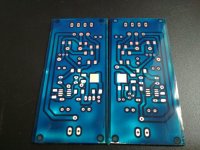
Now I need to do a sanity check of my layout and make the negative PCB version.
Ideally, the emitter of the pass device should be as close to the output pins as possible. The voltage divider resistors should be 1206, and the run to the +Sense, -Sense should be the same length.
It's not compulsory to use the LM329, it turns out to be a great reference at a very reasonable price. Different reference will demand a recalculation of the voltage divider.
You don't need an enormous heat sink -- the pass device will only burn a bit more than a watt. Consider cheating and use a resistor ahead of the super-regulator to burn some energy if your supply runs to over 20 VDC.
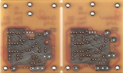
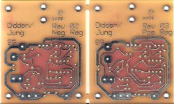
Attached are images of the original SR boards which were supplied by Old Colony back in the 1990's:
Attachments
Great.Thank you!
Not the current version, I'm working on it. But check with Hans, I have the feeling that his preamp will work fine with +/- 15V.
Jan
The phono stage have onboard LDOs (LT1763 & LT1964-BYP) and they are set to deliver ca. +/- 15.7V. I can make it work by replacing the LDOs with the SilentSwitcher.
Thank you jackinnj for your valuable feedback.
Ideally, the emitter of the pass device should be as close to the output pins as possible. The voltage divider resistors should be 1206, and the run to the +Sense, -Sense should be the same length.
It's not compulsory to use the LM329, it turns out to be a great reference at a very reasonable price. Different reference will demand a recalculation of the voltage divider.
You don't need an enormous heat sink -- the pass device will only burn a bit more than a watt. Consider cheating and use a resistor ahead of the super-regulator to burn some energy if your supply runs to over 20 VDC.
Attached are images of the original SR boards which were supplied by Old Colony back in the 1990's:
I know those PCBs
Jan
Hello, recently I build regulator (first positive side) and have no regulation at output. Green led lights up but are dim.
Measured some voltages:
Vin: 19.2V
Vout with 470ohm load: 18.2V
Gnd to op-amp pin2: 11.03V
Gnd to pin 3: 11.56V
op-amp supply: 18.2V
Gnd to pin6: 17.08v
Gnd to LM329 pin2: 12.15.
Any suggestions?
Measured some voltages:
Vin: 19.2V
Vout with 470ohm load: 18.2V
Gnd to op-amp pin2: 11.03V
Gnd to pin 3: 11.56V
op-amp supply: 18.2V
Gnd to pin6: 17.08v
Gnd to LM329 pin2: 12.15.
Any suggestions?
Hello, recently I build regulator (first positive side) and have no regulation at output. Green led lights up but are dim.
Measured some voltages:
Vin: 19.2V
Vout with 470ohm load: 18.2V
Gnd to op-amp pin2: 11.03V
Gnd to pin 3: 11.56V
op-amp supply: 18.2V
Gnd to pin6: 17.08v
Gnd to LM329 pin2: 12.15.
Any suggestions?
There should be not more than 7V across the '329. Did you measure on the pcb or on the pins of the device itself? Is the LM329 soldered correctly? Is there continuity from the leads at the body to the pcb tracks?
If you measured on the '329 pins and its more than 7V, it is broken.
Jan
There should be not more than 7V across the '329. Did you measure on the pcb or on the pins of the device itself? Is the LM329 soldered correctly? Is there continuity from the leads at the body to the pcb tracks?
If you measured on the '329 pins and its more than 7V, it is broken.
Jan
I measure on pins and across j2-4 to R4, same result. But now I try to measure voltage on LM329 pin 3(gnd) to pin 1 (unused) and I read 5.72V, but this value is to low. Maybe my LM329 is different from datasheets found on internet.
Last edited:
I measure on pins and across j2-4 to R4, same result. But now I try to measure voltage on LM329 pin 3(gnd) to pin 1 (unused) and I read 5.72V, but this value is to low. Maybe my LM329 is different from datasheets found on internet.
Why are you measuring an unused pin??
What is the voltage between the two used pins?
Are you sure the '329 is inserted correctly? Are you using the diyaudio PCB?
Why are you measuring an unused pin??
What is the voltage between the two used pins?
Are you sure the '329 is inserted correctly? Are you using the diyaudio PCB?
As I say, voltage between lm329 2-3 pins is 12.15V.
I will try to turn it 180 degrees because I fink I use pin numbers not from bottom but from top view.
Last edited:
turned lm329 and now it works as it should be. Thank you didden for help.As I say, voltage between lm329 2-3 pins is 12.15V.
I will try to turn it 180 degrees because I fink I use pin numbers not from bottom but from top view.
Last edited:
turned lm329 and now it works as it should be. Thank you didden for help.
Yes, top view or bottom view, that has bitten me too!
Jan
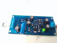
Some photos of my build. It is dual sided home made pcb
Dissipation is current through pass device * voltage across the pass device.
How much current is 6 * AD797? Is in the data sheet, supply current.
How much voltage across the pass device? Vout = 6V, what is the input voltage?
You can do the sums. Once you know the dissipation, we can see if a heatsink is required or not.
(And please you guys out there who want to promote your favorite heatsink: I am trying to help him find it himself. Please don't spoil it).
Jan
ad797 Quiescent Current 8.2-10.5mA (so I fink it will be about 5mA over positive ant 5mA over negative rail?) So for 6xAD797 it will be 30ma or 60mA on positive side? Input voltage will be about 25V output 12v. Now with 60mA at output where is no heating.
ad797 Quiescent Current 8.2-10.5mA (so I fink it will be about 5mA over positive ant 5mA over negative rail?) So for 6xAD797 it will be 30ma or 60mA on positive side? Input voltage will be about 25V output 12v. Now with 60mA at output where is no heating.
If the data sheet says 10mA it is the current from the V+ through the device out of the V-, so each supply needs to give 10mA.
So for both the pos and the neg you are faced with 60mA current or 0.06A.
Now you say Vin = 25 and Vout = 12V. (Before you said 6V). So the pass device sees 25 - 12 = 13V.
So the dissipation is 0.06 * 13 in Watt. The pass device, if it is TO-220, should be able to survive that with a screw-on heatsink, no need for a large PCB-mounted heatsink.
Your Vin of 25V is quite high for 12V out. It will work of course, but if you can lower the 25V down to say 18V or even 15V, the dissipation would drop a lot and there will be even less heat.
BTW You are hiding your profile, so don't know whether English is your native language, but it is 'I think' not 'I fink'.
Jan
Last edited:
I
BTW You are hiding your profile, so don't know whether English is your native language, but it is 'I think' not 'I fink'.
Jan
Fink can be used as a noun or verb.
- Home
- The diyAudio Store
- Super Regulator