I am about to embark on a super reg build. Want to use it to feed my Pass BA-3 based preamp with 24V rails. This is a complicated build for me...I've read the guide and every post in this thread but any suggestions are welcome.
Plan to use a 24V transformer into Peter Daniels PS boards w/MUR860 diodes and then 2 2,200uf caps in a CRC arrangement...probably use 4 .47ohm 3 watt resistors between the caps. This will come before the super reg.
I have AD817ANZ I plan to use for the ICs. And 100uf 35V silmic caps to use on the super reg board. These are low-esr caps...too low to use on the output?
I plan to use 2.5K resistors to get the 24V...because according to Jan:
The Vout is set by the two resistors that feed the inverting input of the opamp, don't remember the exact reference # right now.
Say you want 18V out. The bottom resistor has the same voltage as the LM329 reference (6.9V) because the inv and non-inv opamp inputs will be at the same voltage.
Then size the top resistor for the remaining 18-6.9=11.1V.
So if the bottom resistor is 1k with 6.9V, the top resistor needs to be 11.1/6.9 times 1k, around 1.6k. Similar for 20V vout, top resistor must be 13.1/6.9*1k= 1.9k.
Makes sense?
So, 2.5K seems like it would give me 24V out. And the AD817 is good up to 40V I think.
Anybody see any issues with this setup?
Try the Silmics at the output, they may be OK, an AD817 is pretty stable. Do you have a way to check for possible oscillations, like an unexplained deviation from the set 24V?
Also make the zener in series with the opamp output nominal 12V (anything between 9 and 18V will work though.
Anything else sounds fine.
To increase success rate, initially short the remote sense lines to the output lines (ground sense to ground and output sense to output). Then if all works fine you can get more adventurous.
Jan
Last edited:
Jan,
Thanks for your reply and for making this board available. You are one of the good guys.
I may start a separate build thread once I get all the parts gathered. Iam hoping for a big improvement over my existing 317/337 supply.
I don't have a scope to check for oscillations but hopefully it will be stable.
The thing to remember is that the +input is at the reference (let's say 6.9V in case of the LM329), so in operation the -input should also have the same voltage.
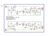
So for 24V output you need to divide down that 24V with R6/R7 (pos reg) and R13/R14 (neg reg) to also 6.9V. (Note that in the schematic you linked, the Vout on the neg reg is at the bottom side so the resistive divider is upside down, as it were, with respect to the pos reg!).
So what's important is the ratio of R6 to R7 (and R13 to R14) not their absolute values (within reason of course).
You can easily see that the voltage across R6 (and R13) MUST be 24V - 6.9V = 17.1V. So if the voltage across R6 is 17.1V and the voltage across R7 is 6.9V, R6 MUST be 17.1/6.9 times R7!
Just pick any convenient value for R7, like 2.2k, and then R6 will be 2.2k * (17.1/6.9) = 5.45k. Sometimes it pays to juggle the values a bit to get to standard values. With R6 = 2k, R7 becomes 4.95k both values being close to standard values.
Of course the output voltage will almost certainly not be 24.0000000V, but who cares - anything between say 23.8 and 24.2 will do.
Nice built btw.
Jan
Last edited:
If there is enough interest, I could develop a high-current version....
Jan
Yes, please
")
Thank you Jan. I get it. This is great info, you probably spelled it out before in your article but for novice builders like me this is great info. A lot of us are building stuff "paint by numbers" style and trying to learn along the way. This is a big help.
For me, the math is easier if we just keep R7/R14 at 1K and adjust R6/R13 to get the right ratio that will allow us to hit the target output voltage.
Target output Voltage - 6.9V (this is the LM329 value) = "X"
"X"/6.9 = "Z"
"Z" multiplied by R7 or R14 value = R6/R13 value
Here are some examples keeping the R7/R14 resistor at 1K and the LM329 value (6.9V), like you said...common resistors values can be used instead to get slightly different voltages other than "exactly" 24V or whatever you are shooting for:
-----------------
24V
24 volts - 6.9 = 17.1V
17.1V/6.9 = 2.478
2.478 times 1K = 2.47K!
R7/R14 = 1K
R6/R13 = 2.47K
-----------------
18V
R7/R14 = 1K
R6/R13 = 1.61K
-----------------
12V
R7/R14 = 1K
R6/R13 = 740R
OK, apparently I hooked up the Positive side of the regulator to reversed voltage. I corrected it but now the LED doesn't come on and I am getting 30V on output when it should be 24...I have 33V in. What is fried? Caps? Transistors? I know I need to replace the LED.
Negative side is working...LED is on but I am only getting 11.4V out. According to my resistor calculations (R13 = 2.47K, R14 = 1K) I should be getting 24V. This is with no load.
Any ideas?
Negative side is working...LED is on but I am only getting 11.4V out. According to my resistor calculations (R13 = 2.47K, R14 = 1K) I should be getting 24V. This is with no load.
Any ideas?
OK, apparently I hooked up the Positive side of the regulator to reversed voltage. I corrected it but now the LED doesn't come on and I am getting 30V on output when it should be 24...I have 33V in. What is fried? Caps? Transistors? I know I need to replace the LED.
Negative side is working...LED is on but I am only getting 11.4V out. According to my resistor calculations (R13 = 2.47K, R14 = 1K) I should be getting 24V. This is with no load.
Any ideas?
If you reversed the voltage on the opamp, that might be fried. LED may still be ok though.
I would replace the opamp and if it still wasn't right, do some measurements. For instance, is the pass transistor B-E not shorted.
Jan
Thanks Jan.
Actually, for the neg side (the one that is working) I've got 14.5V on the output between V- and ground. And I have 8V between V- sense and ground.
So add these two together and I've got 24V! I didn't realize the sense lines actually carried voltage...I thought they were just a "sensor" of sort. So I guess just measuring between V- out and ground is not going to give you an accurate measurement of output. You need to add the V out of the sense line as well?
Thanks Jan.
Actually, for the neg side (the one that is working) I've got 14.5V on the output between V- and ground. And I have 8V between V- sense and ground.
So add these two together and I've got 24V! I didn't realize the sense lines actually carried voltage...I thought they were just a "sensor" of sort. So I guess just measuring between V- out and ground is not going to give you an accurate measurement of output. You need to add the V out of the sense line as well?
But the V- sense needs to be connected to V- so there cannot be a difference between the two....
Please read the article about the regulator, it will be clear then.
Jan
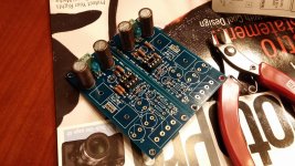
Superregulator is up and running. THANK YOU JAN.
I got a little over my head but its really not a difficult build. Sounds good so far...Ill post some listening impressions after it gets a chance to burn in and i get some time to get a good listen. Again, than you Jan, not only did you make the board available but also held my hand through the build. Couldn't have done it without you.
I got a little over my head but its really not a difficult build. Sounds good so far...Ill post some listening impressions after it gets a chance to burn in and i get some time to get a good listen. Again, than you Jan, not only did you make the board available but also held my hand through the build. Couldn't have done it without you.
Attachments
Well done! So what's your next project
Looks like a well-executed build, btw.
Jan
Next project? Likely a phono stage. Currently I am using a JFET-based phono stage (La Pacific style). Any recommendations?
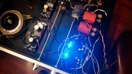
I have had the Superreg powered up for about 24 hours...It replaced a LM317/337 regulator. I have to say the super regulator is an improvement. Detail improvement is great. Imaging is a little tighter and better locked in. I had to lower the rail voltage of the Pass BA-3 based preamp I am using it in to get the 5V drop of the superreg (it is now 25V, it was 30V) but things seem cleaner/tighter overall. It just seems a little more real and natural.
- Home
- The diyAudio Store
- Super Regulator