I'll guess we know the truth when we can see one. I'm not sure either which regulator type is the best in terms of regulation properties.
I have just downloaded the article but when you read such an old document you must be extra careful if some of the facts are based on available parts. This means that some of the content may be false today but was true back then.
I have just downloaded the article but when you read such an old document you must be extra careful if some of the facts are based on available parts. This means that some of the content may be false today but was true back then.
Hi,
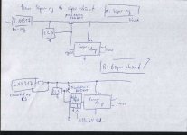
here is a conceptual sketch of my idea. If there is some interest in discussing it, it might be best to split this into a new thread, if not, its a footnote...
Please note that my circuit is not the ALW circuit, but the 2002 jung-didden circuit.
Is my thinking correct, that we need an additional 'beta-booster'?
thanks,
Rüdiger
@Per-Anders: I tried a simple one-fet amp with LTSpice, but even don't get the DC-operating points, let alone square wave response or the like...
Attachments
Hi,
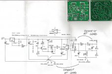
i use the attached board. It is very similar to alw's version, but it does not have the extra driving transistor for the pass device, T2.
I had a ztx450, so I added this transistor in the place of R5 (10R) and changed R3 from 249R to 100R.
It is the almost the same circuit now. but it does not work, I get 6Volts out instead of 15V.
What happens there?
Rüdiger
Attachments
Hi,
despite from my non-solved problem above,
I wonder about the optimal opamp-decoupling in connection with the super reg: Since it is said, don't use large uF after the superreg, will decoupling caps on the opamp pins need to be smaller than normal (say, smaller than 100uF)?
Rüdiger
despite from my non-solved problem above,
I wonder about the optimal opamp-decoupling in connection with the super reg: Since it is said, don't use large uF after the superreg, will decoupling caps on the opamp pins need to be smaller than normal (say, smaller than 100uF)?
Rüdiger
aos' boards are cheap and no support is included what so ever (this is clearly stated but not very good when support is needed  )
)
Have you checked the pinning of the small signal transistor?
American types are E-B-C, european model C-B-E
About decoupling, yes not too much. 100 uF or so is a good start and if you want more for some reason you might verify this with measurements. An oscilloscope is necessary.
The idea behind the regulator is to create in an artificial way low output impedance and the chance for this is good since the board can handle AD825.
)Have you checked the pinning of the small signal transistor?
American types are E-B-C, european model C-B-E
About decoupling, yes not too much. 100 uF or so is a good start and if you want more for some reason you might verify this with measurements. An oscilloscope is necessary.
The idea behind the regulator is to create in an artificial way low output impedance and the chance for this is good since the board can handle AD825.
Re: Re: Re: SMT SuperRegulator
hard to believe that this thread has gone dormant -- my super regulators with through-hole devices work just fine but the version i built with surface mount components (substituting MJD44H11 and MMBT5087, smt leds, zeners and clamp diodes etc.,) suffers from the "false-start" syndrome -- the footprint is 3.5 x 2.5 inches for one board with positive and negative regulators.
peranders said:
Anything to show?
hard to believe that this thread has gone dormant -- my super regulators with through-hole devices work just fine but the version i built with surface mount components (substituting MJD44H11 and MMBT5087, smt leds, zeners and clamp diodes etc.,) suffers from the "false-start" syndrome -- the footprint is 3.5 x 2.5 inches for one board with positive and negative regulators.
Here's a picture of the negative side regulator -- this is a proto with no silk, and I think I will go to SMT LM337's -- the size can probably shrink by 25% or so -- I've provisioned for the +/- SENSE wires but they are jumpered here:
An externally hosted image should be here but it was not working when we last tested it.
Can't see but have you an emitter follower down to ground from the opamp output? The zener arrangement should create 7-9 volts at the output in order to give supply voltage to the opamp. Have you as a test tried to feed the opamp from the unstablized side (after the LM337)?
here's an a.c. coupled scope-shot of the negative regulator output -- the transistors are MJD45H11 and MMBT5088 -- the trace has been averaged 16X for better clarity -- this is 10.4 millivolts RMS at 1 MHz -- there are no compensation capacitors on the AD825.
Same thing with 300 pF compensation caps (WJ recommended 100pF, but I don't have any SMT 100pf's, drat!)
An externally hosted image should be here but it was not working when we last tested it.
Same thing with 300 pF compensation caps (WJ recommended 100pF, but I don't have any SMT 100pf's, drat!)
An externally hosted image should be here but it was not working when we last tested it.
jackinnj said:here's an a.c. coupled scope-shot of the negative regulator output -- the transistors are MJD45H11 and MMBT5088 -- the trace has been averaged 16X for better clarity -- this is 10.4 millivolts RMS at 1 MHz -- there are no compensation capacitors on the AD825.
An externally hosted image should be here but it was not working when we last tested it.
Not nice - what's your final output cap? Type, value? I guess you have a prereg - does the prereg show something like this on its output?
Jan Didden
the oscillation occurs with the LM337 pre-regulator -- the positive SR with no pre-regulator doesn't show any oscillation.
I am using Panasonic FC's 120u/25V.
It isn't apparent from the Audio Elec article of 4/2000 whether WJ performed the same extensive testing on the pre-regulated SR as was the case in the 1995 series. I have to read the series again.
Here's a snapshot of the SR output and the output of the LM337 -- "be some serious modulating going on down there Amos"
An externally hosted image should be here but it was not working when we last tested it.
- Status
- This old topic is closed. If you want to reopen this topic, contact a moderator using the "Report Post" button.
- Home
- Amplifiers
- Power Supplies
- Super Regulator, collecting the facts