Yes, there is a difference between what you expect from a coupling cap versus a decoupling cap.
In a coupling cap, you want the signal on one end to be identical to the signal coming out on the other side (possibly lower in level, or frequency-dependent level as in a filter, but identical in shape). So you don't want ERS or absorbtion effects, and a film capacitor is good choice here.
In a regulator the cap at the output of the regulator is there only to assure stability. Some ESR and/or absorbtion is good here as it damps any oscillatory tendencies. In fact, if you look at some data sheets of low drop-out regulators, they used to spec a MINIMUM ESR for stability. These low-dropouts often use PNP pass transistors, which generally have lower Ft than NPNs and will oscillate quicker in a feedback regulator.
Some of the latest low-dropouts are advertised with the fact that they are stable WITHOUT ESR in the final cap so designers can use less costly ceramic caps.
jan
yep, for the same reason many of the high performance low noise LT LDOs require some ESR still, particularly if they are a ways away from the load in a battery operated scenario due to L in the long lines. whether that is brought about by controlled impedance traces, using a smaller electrolytic cap with not so ridiculously low ESR like many polymers, or inserting some series R to damp resonance depends on the job i guess.
thanks for fleshing that out Jan, ive mentioned a few of these type issues in the recent superreg threads these guys are involved in, but they dont really want to listen to me, some seem to just want to throw money and high performance parts at the problem without thinking it through. the super-reg generally uses pretty wide band low noise FAST high performance opamps and needs to be treated accordingly.
thanks for fleshing that out Jan, ive mentioned a few of these type issues in the recent superreg threads these guys are involved in, but they dont really want to listen to me, some seem to just want to throw money and high performance parts at the problem without thinking it through. the super-reg generally uses pretty wide band low noise FAST high performance opamps and needs to be treated accordingly.
Hi,
Here is a version of the super reg I just got as part of a TDA1543 DAC. What do you think ?
Cheers,
Tom
Here is a version of the super reg I just got as part of a TDA1543 DAC. What do you think ?
An externally hosted image should be here but it was not working when we last tested it.
Cheers,
Tom
GOLD Reference Mini regulator
A variant of well know Jung-Didden regulator.
Replace ZD1 with LED, replace TL431 voltage reference with LED, increase cap across feedback resistor (C7). For low voltage output, 5V and similar, you can throw away D5, D6, D7.
When output voltage is set, measure VR1 resistance. R6 (3K) and measured resistance (VR1) are in parallel, calculate total resistance. Parallel resistor calculator. Make R5 the same value as calculated resistance.
Example: R6 = 3K, VR1 = 3K. Total resistance = 1.5K, then R5 = 1.5K.
R5 and C5 are LPF for voltage reference. C5 should be low-leakage type, no OSCON cap there! Panasonic FC and FM are cheap and work OK, even tantals are OK there (if you like them).
Your ears will be grateful
Last edited:
GOLD Reference Mini regulator
A variant of well know Jung-Didden regulator.
Replace ZD1 with LED, replace TL431 voltage reference with LED, increase cap across feedback resistor (C7). For low voltage output, 5V and similar, you can throw away D5, D6, D7.
When output voltage is set, measure VR1 resistance. R6 (3K) and measured resistance (VR1) are in parallel, calculate total resistance. Parallel resistor calculator. Make R5 the same value as calculated resistance.
Example: R6 = 3K, VR1 = 3K. Total resistance = 1.5K, then R5 = 1.5K.
R5 and C5 are LPF for voltage reference. C5 should be low-leakage type, no OSCON cap there! Panasonic FC and FM are cheap and work OK, even tantals are OK there (if you like them).
Your ears will be grateful
Hi,
Great reply - thanks !
I already changed zd1 for lm336. Would 3 red leds be quieter ?
Are you sure R6 is in parallel with VR1 ? It looks like a potential divider to set the gain ?
I was thinking about changing both zd1 and tl431 to lm329 to set 6.9v minimum voltage.
I'm using opa690 (500Mhz, 190mA output, 1800uV/s slew, 5.5nV noise) as the op amp and BUP41 (120Mhz, hfe 200) as pass transistor, and it is driving 16x tda1543 - so there is more than enough current available - but I think I should be able to increase the bandwidth too by lowering C7 ?
Thanks again.
Tom
From that site : it's the same !
An externally hosted image should be here but it was not working when we last tested it.
Last edited:
I'm afraid with a not optimal pcb layout since you can't get a stable function using AD825. The signal ground is not correctly designed on the pcb. I have the pcb myself and it doesn't work on higher speeds but using OPA134 would probably work good.
Would 3 red leds be quieter ?
Yes, few orders of magnitude.
Are you sure R6 is in parallel with VR1 ? It looks like a potential divider to set the gain ?
Yes, it is potential divider to set gain. But opamps inverting input is considered as "virtual ground", therefore R6 is parallel to VR1.
I was thinking about changing both zd1 and tl431 to lm329 to set 6.9v minimum voltage.
Whatever you want
But LED's as voltage reference are much quieter than Zeners and Zeners are much quieter as bandgaps.
I'm using opa690 (500Mhz, 190mA output, 1800uV/s slew, 5.5nV noise) as the op amp and BUP41 (120Mhz, hfe 200) as pass transistor, and it is driving 16x tda1543 - so there is more than enough current available - but I think I should be able to increase the bandwidth too by lowering C7 ?
R6 is feedback resistor and VR1 is gain set resistor. Together they are potential divider to set gain. DC gain should remain constant, but AC gain should be low as possible and you need big cap across feedback resistor to lower AC gain. Everything is very well explained on Walt Jung website.
Let me ask something:
Why do you need high bandwith? Because it is "digital" circuit and regulator should work well into MHz range?
Then you are wrong.
Lets see your opamp, OPA690: Unity gain stable @ 500 MHz (G=1), Input voltage noise 5.5nV, Input current noise 3.1pA. Everything look OK, but it is really perfect for this job?
For digital clocks, D/A converters,..everything where clock is present and of importance, you need low noise. But not low noise @ 100kHz, low noise @ 1-100 Hz, low 1/f noise. OPA690 is specified as 5.5nV input voltage noise @ f > 1 Mhz. Look at Figure 13 in datasheet, where currrent and voltage noise are plotted. Graph starts with 100 Hz and there is 10nV input voltage noise. If you can imagine lower frequency, what will be noise @ 10 Hz? 100nV?
What will be @ 1 Hz? Much worse than 100 nV. Same thing with current noise.
Opamp noise
Better choice will be precision opamp, low 1/f knee, low 1/f noise, low overall voltage & current noise and with moderate speed. Not super-fast opamp with super wide bandwith, since those super-fast opamps have usually poor low frequency noise specifications.
Better choice will be precision opamp, low 1/f knee, low 1/f noise, low overall voltage & current noise and with moderate speed. Not super-fast opamp with super wide bandwith, since those super-fast opamps have usually poor low frequency noise specifications.
The AD797 wins hands down in the measurement category, but it is finicky. Take the time to read the articles which are archived on Walt Jung's website.
I found that the LME49710 came close to the AD797 in terms of PSRR, Noise and Zo but haven't had the opportunity to run it past the listening panel.
You can force the AD797 into heart-attack mode. It's an expensive experiment.
Hi,
Many thanks for the replies.
I have changed the Oscons to Nichicon Fine Gold and in the process the red led has quit its fluttering. This could be coincidence but I suspect it was a soldering issue.
The only reason for more bandwidth is to control the DAC ICs better. However, the PCB is poor so I can give up on that. Of course, I want low and constant noise, low and constant output impedance, etc etc. But do I need it ? Well, I suspect the tda1543 doesn't really benefit beyond a certain level because of its own limitations.
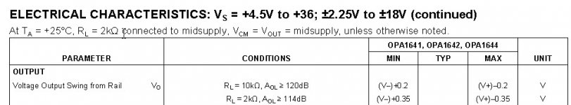
I read Walt Jung's articles and it seems like the opa1641 is actually quite a good choice.
The noise doesn't rise too much at low frequencies ( 8nV @ 10Hz ) and the jfet input keeps current noise low etc, plus it is rail to rail down to 5V supply, and an open loop gain of over 120dB. Output current is 30mA so that should be enough for this circuit and 16x tda, given I'm also using the high hfe pass transistor.
I now understand why the feedback gain resistors work in parallel. I will have something like 4K and 9K so that will be something around 2.7K on the input to the op amp. Seems quite high ?
I think that the best way to get this reg better now is to use some copper sheet to improve the grounding, and then I can see if I can lower the noise levels; replace the zd1 with three red leds ( not too much current flowing there ? I seem to remember their lowest noise is around 5mA ) , and create a better vref than the tl431.
Again, thank you all for your help !
Cheers,
Tom
Many thanks for the replies.
I have changed the Oscons to Nichicon Fine Gold and in the process the red led has quit its fluttering. This could be coincidence but I suspect it was a soldering issue.
The only reason for more bandwidth is to control the DAC ICs better. However, the PCB is poor so I can give up on that. Of course, I want low and constant noise, low and constant output impedance, etc etc. But do I need it ? Well, I suspect the tda1543 doesn't really benefit beyond a certain level because of its own limitations.
I read Walt Jung's articles and it seems like the opa1641 is actually quite a good choice.
The noise doesn't rise too much at low frequencies ( 8nV @ 10Hz ) and the jfet input keeps current noise low etc, plus it is rail to rail down to 5V supply, and an open loop gain of over 120dB. Output current is 30mA so that should be enough for this circuit and 16x tda, given I'm also using the high hfe pass transistor.
I now understand why the feedback gain resistors work in parallel. I will have something like 4K and 9K so that will be something around 2.7K on the input to the op amp. Seems quite high ?
I think that the best way to get this reg better now is to use some copper sheet to improve the grounding, and then I can see if I can lower the noise levels; replace the zd1 with three red leds ( not too much current flowing there ? I seem to remember their lowest noise is around 5mA ) , and create a better vref than the tl431.
Again, thank you all for your help !
Cheers,
Tom
Last edited:
Too late to edit - I tried the 2K7R and that works. Thanks !
So I'm now looking at replacing the 5V lm336 on the output of the op amp with something better. LM336 has about 20uV noise according to the datasheet.
For the voltage ref, the fet ccs is a 2SK30GR which has an Idss of between 0.3mA and 6.5mA according to the datasheet, with the GR being the highest, so it should be enough to drive some red leds. Most posts I've found indicate something around 4-6mA.
According to this post the 2sk30GR is quiet :
Recommend JFETS for audio
So it looks like 3 or 4 red leds will be the best choice for vref ? The noise increases by rt I believe, so 4 leds = double the noise ?
So if this is the case, why doesn't the original design use leds for vref driven by a jfet cascode ?
Thanks,
Tom
So I'm now looking at replacing the 5V lm336 on the output of the op amp with something better. LM336 has about 20uV noise according to the datasheet.
For the voltage ref, the fet ccs is a 2SK30GR which has an Idss of between 0.3mA and 6.5mA according to the datasheet, with the GR being the highest, so it should be enough to drive some red leds. Most posts I've found indicate something around 4-6mA.
According to this post the 2sk30GR is quiet :
Recommend JFETS for audio
So it looks like 3 or 4 red leds will be the best choice for vref ? The noise increases by rt
I believe, so 4 leds = double the noise ?So if this is the case, why doesn't the original design use leds for vref driven by a jfet cascode ?
Thanks,
Tom
Last edited:
please forget the idea that the opamp bandwidth somehow has effect on IC that operates at high speed. any fast transients will be handled by the local decoupling caps, the regulator will have nothing to do with it. for a regulator for clock and dac you want stable low noise and low output impedance, the bandwidth is nice and all, but not as important as these factors. Stormsonic is absolutely correct, clock and dac phase noise/jitter is most effected by low frequency noise where most devices have lower PSRR. clocks in particular, though they operate at high frequency, are about as stable a load as you will find, transient response has little meaning, low frequency noise does
LEDs are quiet, but not so stable over temperature, this may be why its not preferred (although has been offered as an alternative in some papers)
also watch out doing too much tweaking on these boards, the PCB is of fairly poor quality and its easy to lift traces
changing the cap to one that is low leakage and not so lowZ could easily be the reason why its more stable now, too low impedance can cause oscillation
Last edited:
Hi,
Thanks for that - I understand decoupling but I didn't know this wasn't affected by the reg's bandwidth...I thought it would all work together.
Yeah, the board is, well, it's like nothing else I've had. Lots of care and patience...
I tried using two red leds = 3.5V to replace the TL431 = 2.5V. Strangely, I needed more gain ?? but the sound seems more dynamic now. That could be placebo...
So that's all good and last thing to try is replacing the 5V lm336 (zd1) with something lower noise.
I have no idea how much current is flowing through that and I'm loathed to try something that might in some way damage the transistors because they are very hard to find, not to mention the problems desoldering the board. Is it worth trying something else ? Any ideas ?
Thanks again !
Hello again,
I just read this (again !):
http://waltjung.org/PDFs/Low_Noise_Power_for_Analog_Circuits.pdf
and I would like to know what would happen if I increase the bootstrap voltage of ZD1, currently 5V, to 5.3V using three red leds, or 6.9V with an lm329 - would this set the minimum output voltage at the bootstrap level ?
To explain my thoughts, I think that the reason I needed more gain, even though vref was higher, was insufficient voltage for the op amp to accept a 3.6V ref... but I am a little confused because the op amp is supposed to be rail-to-rail at a minimum single supply of 4.5V....could there be a loss due to the input diodes ?
I also read this where it says the vref and the bootstrap should be similar :
http://waltjung.org/PDFs/Regulator_Excels_In_Noise_and_Line_Rejection.pdf
but in the circuit I bought vref was 2.5 and bootstrap was 5.6V.
Thanks for any help !
Cheers,
Tom
Last edited:
THANKS !
Hi,
I finished all these changes.
I used two leds as vref.
I tried 4 leds (6.99V) as the bootstrap voltage (ZD1) but the reg wouldn't start and just passed through 6.8V so then I used 3 and this works fine.
I still don't really get why the circuit fails the way it does, so I'd like to see a SPICE model but nevermind - it works and sounds very good.
Thank you very much for your advice !
Tom
Replace ZD1 with LED,
replace TL431 voltage reference with LED,
increase cap across feedback resistor (C7).
When output voltage is set, measure VR1 resistance. R6 (3K) and measured resistance (VR1) are in parallel, calculate total resistance. Make R5 the same value as calculated resistance.
R5 and C5 are LPF for voltage reference. C5 should be low-leakage type, no OSCON cap there! Panasonic FC and FM are cheap and work OK, even tantals are OK there (if you like them).
Your ears will be grateful
Hi,
I finished all these changes.
I used two leds as vref.
I tried 4 leds (6.99V) as the bootstrap voltage (ZD1) but the reg wouldn't start and just passed through 6.8V so then I used 3 and this works fine.
I still don't really get why the circuit fails the way it does, so I'd like to see a SPICE model but nevermind - it works and sounds very good.
Thank you very much for your advice !
Tom
If you have a LM431 it's critical how you choose the feedback resistors for the LM431 in combination with the actual gain. The non-inverting input (pin 3) must be higher than pin 2 under startup, otherwise nothing will happen. ZD1 must be chosen with taste. It depends how high your output voltage is. The goal is that the output of the opamp is in it's active range. ZD1 is a level shifter you know.
No offense, but if you redesign the circuit you must know what good each component does.
BTW: What output voltage do you want? Output current?
Input voltage?
No offense, but if you redesign the circuit you must know what good each component does.
BTW: What output voltage do you want? Output current?
Input voltage?
No offense taken - I'm learning (fast I hope), and I'm simply happy you are willing to help.
The reg is driving 16x tda1543 so the output voltage needs to be adjustable between 6 and 8.5V with up to 1A output. There is a separate psu for the digital circuits so this one is just for the tda. It uses opa1641.
I switched transformers for a higher VA and that solved the 4 leds as zd1. The input voltage was dropping too much so there was not enough headroom. Very basic mistake eh ?
However, I still don't understand why I needed higher gain when I replaced the tl431 (R and C shorted to produce 2.5V as vref) with 2 leds (3.6V). Surely I would need less gain ? This is what has got my head muddled and it is why I'm thinking I've misunderstood.
Anyway, now I'm thinking about a fully discrete version. The op amp could be replaced with a current mirror driving a long tailed pair, loaded by cascoded jfet ? Could this be lower noise, etc etc ? Has anyone done a circuit/simulation/pcb for this ?
Thanks again for the help !
Why do you need 4 LEDs as replacement for ZD1? ZD1 is used as level shifter and with 4 LEDs and with 6V output you are pushing opamps output bellow neg power supply???
You have pure luck, since OPA1641 is capable to swing that low, almost to the neg power supply rail
Your voltage reference: how do you calculate gain?
Another issue: watch for OPA1641 input range
You have pure luck, since OPA1641 is capable to swing that low, almost to the neg power supply rail
Your voltage reference: how do you calculate gain?
Another issue: watch for OPA1641 input range
Attachments
Last edited:
haha... a bit of luck but not pure luck ;-) I might be a blind man in a dark room looking for a black cat... but I can still hear it ;-) I chose it because it was rail to rail, among other things. I read and re-read the Jung article about this so I know it is a good op amp for this application. Thanks to the people here I discarded the opa690 in favour of the opa1641.
I don't need or want 4 leds for zd1. I tried because the situation I am investigating is this :
The original voltages were 5.6v for zd1 and 2.5v for vref. 5.6V is enough to start up the op amp. I changed zd1 to 5V (lm336) and this still worked fine for a 6V output into 4x tda1543 (200mA).
I then changed vref to 2x red led. I tested them before I fitted them with a 4mA ccs (2sk30GR, same as in the circuit) and the voltage drop across them was 3.55V. However, when I fitted them I found I needed more gain to get a 6V output. This is the cause of my confusion. As I understand it, the gain is set by the potentiometer at the output providing negative feedback. 3.3KR and 10KVAR. When I start up, I have 3.3KR and 10KR (actually 9.6KR) to measure the min voltage out, and then I change the gain to see how it responds.
So I tried 4 leds because I wanted to see what effect the higher zd1 voltage would have on the need for gain. I was wondering
1) if I need a higher zd1 than vref - Jung's article says they should be the same, and this makes perfect sense to keep the op amp's differential input voltage as low as possible, but I'm curious, and/or
2) if an increased zd1 will lead to less gain, and/or
3) if an increase in vref will lead to less gain (the opposite happened)
4) what happens when I fully load the circuit with 16x tda1543 (~800mA) - stability, dropout, pass transistor dissipation, op amp loading, etc..
Basically, I was trying to undertand why I needed more gain when I increased vref - the opposite effect to my logic.
I think the next thing to try is to have 3 leds in both positions.
Ultimately, I'd like to have the min voltage out with min gain to be 6V but actually I'm more concerned with fully understanding this circuit.
Thanks for any help !
I don't need or want 4 leds for zd1. I tried because the situation I am investigating is this :
The original voltages were 5.6v for zd1 and 2.5v for vref. 5.6V is enough to start up the op amp. I changed zd1 to 5V (lm336) and this still worked fine for a 6V output into 4x tda1543 (200mA).
I then changed vref to 2x red led. I tested them before I fitted them with a 4mA ccs (2sk30GR, same as in the circuit) and the voltage drop across them was 3.55V. However, when I fitted them I found I needed more gain to get a 6V output. This is the cause of my confusion. As I understand it, the gain is set by the potentiometer at the output providing negative feedback. 3.3KR and 10KVAR. When I start up, I have 3.3KR and 10KR (actually 9.6KR) to measure the min voltage out, and then I change the gain to see how it responds.
So I tried 4 leds because I wanted to see what effect the higher zd1 voltage would have on the need for gain. I was wondering
1) if I need a higher zd1 than vref - Jung's article says they should be the same, and this makes perfect sense to keep the op amp's differential input voltage as low as possible, but I'm curious
, and/or 2) if an increased zd1 will lead to less gain, and/or
3) if an increase in vref will lead to less gain (the opposite happened)
4) what happens when I fully load the circuit with 16x tda1543 (~800mA) - stability, dropout, pass transistor dissipation, op amp loading, etc..
Basically, I was trying to undertand why I needed more gain when I increased vref - the opposite effect to my logic.
I think the next thing to try is to have 3 leds in both positions.
Ultimately, I'd like to have the min voltage out with min gain to be 6V but actually I'm more concerned with fully understanding this circuit.
Thanks for any help !
Last edited:
- Status
- This old topic is closed. If you want to reopen this topic, contact a moderator using the "Report Post" button.
- Home
- Amplifiers
- Power Supplies
- Super Regulator, collecting the facts