I also tried the alternate connection of the electrolytic cap C3 which bypasses the zener diode string per Walt's suggestion. Unfortunately, this made the 50 MHz parasitic in the pass elements come back. I believe what's going on is that at VHF frequencies, the real part of the input impedance of Q4 is going negative. R7 seems to cure this, but connecting C3 to the base of Q4 provides a low impedance to the base of Q4, bypassing R7 and reintroducing the parasitic oscillation. I don't think the noise will be affected too badly, as there's so much gain ahead of this point from the op-amp that the front end should dominate. That is, the composite noise factor Ftot as below
Ftot = F1 + (F2-1)/G1
should be dominated by F1, since G1 is large in the audio band. At any rate, since this is for a power amp application, noise is not as critical as for the classic version of the super reg. Line rejection and clean, fast transient response to pulses of load current (from charging the gates of the MOSFET output stage) are the most important criteria for me.
Or maybe another approach
"I also tried the alternate connection of the electrolytic cap C3 which bypasses the zener diode string per Walt's suggestion"
At 50 MHz and electrolytic cap looks inductive due to parasistics. Keep the electrolytic bypass, add another 10 ohm resistor between the base of the pass transistor of and your filtered zener stack output. Add a 0.01uF cap directly from the output of the follower (at the other end of filtered zener stack) to the 10 ohm resistor (the end not going to the base of the output transistor). Use a noninductive cap like a ceramic or stacked film mylar and make path as short as possible (for low parasitic inductance) from the added emitter high frequency coupling cap (0.01uF) to the base resistor for output transistor. I'll bet you this will work.....
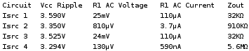
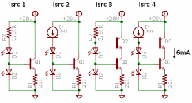
Current sources compared
The banter between Jung and the rest was irresistible, so I was compelled to test these current source ideas out on the bench. I compared the canonical current source with an LED and transistor (Isrc 1), Isrc 1 with a J511 biasing the LEDs (Isrc 2), Isrc 1 with a cascode transistor (Isrc 3), and Isrc 2 with a cascode transistor (Isrc 4). I tested Zout of each current source with a 3.3V 120Hz ripple on the Vcc line. Isrc 4 was the winner by far, with a Zout at 5.6MΩ
The banter between Jung and the rest was irresistible, so I was compelled to test these current source ideas out on the bench. I compared the canonical current source with an LED and transistor (Isrc 1), Isrc 1 with a J511 biasing the LEDs (Isrc 2), Isrc 1 with a cascode transistor (Isrc 3), and Isrc 2 with a cascode transistor (Isrc 4). I tested Zout of each current source with a 3.3V 120Hz ripple on the Vcc line. Isrc 4 was the winner by far, with a Zout at 5.6MΩ
Attachments
Bricolo said:The 4th clearly looks like a winner here. And isn't soo much more complicated.
Jwb: have you also run an AC analysis?
As I said, I tested the impedance at 120Hz. I'm not really equipped to test other frequencies, do sweeps, or what-have-you. Would be an interesting simulation for a SPICE-head.
Would you believe a ........
I believe that the Isrc 4 must have been using a J501 and not a J511. The current for the J511 is about 4.7 mA and that for the J501 is about 0.33 mA. The dynamic impedance for the J511 is around 300 K and that of the J511 typically 10 Meg. With I = (6-0.33) mA across 221 ohms the voltage across the resistor is around 1.2 volts. Add this to the base emitter drop and you get about 1.8 volts for the LED. which would make it a green one.
Sorry about that Chief,
Fred
Attachments
Sorry Fred I don't understand your point. Current diode used was in fact J511, 4.7mA. It was the only one I had laying about, as I used the last of the J506 on Saturday. LED used was LN342GP, a green one that drops 1.9V at 5mA. I used two ZTX869 because they were already on the breadboard.
Do you disagree that the fourth topology is the best one, or are you saying it would have been better had I used a more reasonable current diode?
Do you disagree that the fourth topology is the best one, or are you saying it would have been better had I used a more reasonable current diode?
andy_c said:[snip]
Per Jan's request, I've shown a plot with a load capacitor of 1 uF, having a series resistance of .01 Ohm and a series inductance of 5 nH. The attenuation at the notch is 33.3 dB, which would correspond to an output impedance of the pass transistor of 0.45 Ohms if it were purely resistive. This is consistent with the 61 mA operating current from the DC current source load. The behavior with the 100 uF cap with 0.25 Ohm ESR is also consistent with that value of pass transistor output impedance. I think this plot shows pretty clearly that a low ESR cap is not good. The notch can be so deep that it forces the loop gain magnitude to unity at a frequency below the notch where the phase is lagging considerably.[snip] I'm now beginning to wonder whether Jan wanted this or to add it in parallel with the 100 uF cap. The Zobel network has been removed for this simulation.
Andy,
Thanks very much for this. It neatly confirms my experiences that the "better" the output cap, the more problems with stability and in fact worse output Z in some freq areas. Counter-intuitive, a good, expensive film cap with low ESR is a nono on these supplies, EXCEPT close at the load, away from the supply, so that the wiring L can correct things. Then again, with remote sensing, it comes back again, UNLESS you use the lp filter in the sense line. It all makes sense (no pun intended).
As far as parallelling the two caps, I woulkd think that for this effect the small low ESR cap would dominate and determine the response.
Jan Didden
Hi,
Good to see some people understand the nature of the beast...
666....
Cheers,
Then again, with remote sensing, it comes back again, UNLESS you use the lp filter in the sense line. It all makes sense (no pun intended).
Good to see some people understand the nature of the beast...
666....
Cheers,
Re: Would you believe a ........
Fred, you wrote J511 for both
According to Vishay:
The J501's dynamic impedance is 2.2M
for the 511, it's 120k
All values are minimums
Fred Dieckmann said:The dynamic impedance for the J511 is around 300 K and that of the J511 typically 10 Meg
Fred
Fred, you wrote J511 for both
According to Vishay:
The J501's dynamic impedance is 2.2M
for the 511, it's 120k
All values are minimums
J501
The typical value of dynamic impedance for a J501 is 10 Meg.
The typical value of dynamic impedance for a J511 is 300K.
I assumed that the JFET CS number might have been a misprint. On looking at the math closer for Isrc 4 one would come out with an LED impedance of about 12 ohms for an impedance of 300K for the J511. I have measurements only to about two mA for the LED but guess this would be a reasonable impedance at 5 mA. The use of a J501 with the LED impedance at 130 ohms at 0.33mA gives about 3 times the rejection of supply noise across the LED, at the cost of greater noise generated by the LED at the lower bias level. Before someone else points it out, it might be worth noting that this current source is feeding a circuit with a few ohms of output impedance. The load is the output impedance of an emitter follower and may not come close to justifying a cascode current source of several Meg for it's bias current.
http://www.vishay.com/document/70196/70196.pdf
Isrc 4 may be overkill, but if you are already going to do Isrc 2, you've blown a volt of dropout already, so Isrc 4 only costs one BJT and one LED = 2 more volts. Total dropout increases ~3V I guess, using J501.
Is there any improvement to be had from a JFET current diode biasing the LM329? Replacing a 5kΩ R with a >MΩ current source should improve the noise at the + input of the error amp, but I'm not sure how much improvement can be expected here as the Vout line is quiet. On the other hand we want absolute silence on our reference voltage. I biased the LM329 that way in a Sulzer regulator with some success.
Is there any improvement to be had from a JFET current diode biasing the LM329? Replacing a 5kΩ R with a >MΩ current source should improve the noise at the + input of the error amp, but I'm not sure how much improvement can be expected here as the Vout line is quiet. On the other hand we want absolute silence on our reference voltage. I biased the LM329 that way in a Sulzer regulator with some success.
Triple cascode anyone?
I guess I can live with a single bipolar and a jfet to bias the LED. There comes a point when cost, PCB layout, and stability issues for more complicated circuits become more trouble than they are worth for an improvement in a particular parameter over that of a simpler circuit. If I was feeding an impedance of several thousand ohms maybe a cascode CCS, but not for biasing a follower. The original point was that the substitution of the Jfet current source for the 10 K resistor brought about more than an order of magnitude improvement in rejection for the current source with a very simple change requiring no PCB modifications. I think all of this does show how underfiltered most voltage references in current are and should make one spend a bit more effort designing the current source for biasing the diff pair in your next amplifier or preamp circuit.
I guess I can live with a single bipolar and a jfet to bias the LED. There comes a point when cost, PCB layout, and stability issues for more complicated circuits become more trouble than they are worth for an improvement in a particular parameter over that of a simpler circuit. If I was feeding an impedance of several thousand ohms maybe a cascode CCS, but not for biasing a follower. The original point was that the substitution of the Jfet current source for the 10 K resistor brought about more than an order of magnitude improvement in rejection for the current source with a very simple change requiring no PCB modifications. I think all of this does show how underfiltered most voltage references in current are and should make one spend a bit more effort designing the current source for biasing the diff pair in your next amplifier or preamp circuit.
J202 data
I just finished some measurements on the Siliconix J202 jfets that I received.
Out of ten pieces 5 were around 1.5 mA Idss and the others around 1 mA Idss.
I measured about 1 Megohm AC impedance at 18 volts drain to source for the 1 mA devices which is a higher impedance than I expected from looking at the data sheets. I ran a simple Spice model for my recommended circuit.
Attachments
Re: And now.... the rest of the story
sorry,my disturbing, MR. Fred.
In my mind,You are an expert. I like your post.Although my English is poor,I had learned more knowledge from your post.
thanks a lot!
I want to know all what you say,but ....some sentences you writed maybe longer to me,I had a lit difficulty to read.

thanks again!!!
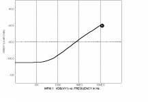
Fred Dieckmann said:Rejection curve for Spice model of the constant current source at the emitter of the pass transistor driver circuit above, for the AWL/Jung regulator.
sorry,my disturbing, MR. Fred.
In my mind,You are an expert. I like your post.Although my English is poor,I had learned more knowledge from your post.
thanks a lot!
I want to know all what you say,but ....some sentences you writed maybe longer to me,I had a lit difficulty to read.
thanks again!!!
Fred,
Interesting curve. >100dB to way above audio. I guess we are over the line of diminishing returns. In practise, PCB leakage, stray capacitance etc will make sure that you stay below this curve. No point in going further, except for mental masturbation (will this go past the censor?).
Jan Didden
Interesting curve. >100dB to way above audio. I guess we are over the line of diminishing returns. In practise, PCB leakage, stray capacitance etc will make sure that you stay below this curve. No point in going further, except for mental masturbation (will this go past the censor?).
Jan Didden
We don't need no steenking simulators, phase I
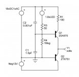
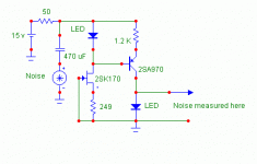
Measured the PSRR of the circuit shown below. The current in each LED is around 1 mA.
I threw it together with the parts that I found close at hand, so I don't want to hear any kvetching about using a 2SK170 as a CCS.
Jocko
Measured the PSRR of the circuit shown below. The current in each LED is around 1 mA.
I threw it together with the parts that I found close at hand, so I don't want to hear any kvetching about using a 2SK170 as a CCS.
Jocko
Attachments
.....phase II...
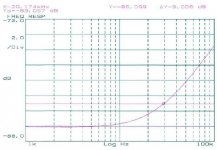
Here is the measured performance of the circuit. Since it may be hard to read (decent pens are getting harder to find at short notice), the data is:
PSRR @ 1 kHz = 86 dB.
PSRR @ 29 kHz = 83 dB.
Not bad for something thrown together, and not optimized.
Jocko
Here is the measured performance of the circuit. Since it may be hard to read (decent pens are getting harder to find at short notice), the data is:
PSRR @ 1 kHz = 86 dB.
PSRR @ 29 kHz = 83 dB.
Not bad for something thrown together, and not optimized.
Jocko
Attachments
- Status
- This old topic is closed. If you want to reopen this topic, contact a moderator using the "Report Post" button.
- Home
- Amplifiers
- Power Supplies
- Super Regulator, collecting the facts