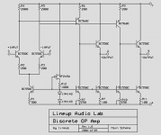
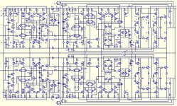
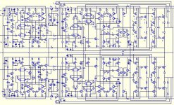
Lineup Standard OP-Amp circuit schematic
this
attachment below
shows my, lineup, attempt to design
one standard general purpose discrete operational amplifier
with very good data
though still fairly straight forward
having some extra added feature
to be even more useful
uses 12T in circuit, all current sources included
12 standard low noise transistors in total
as I have already my own updated, improved and trimmed version done
I can give away this first published version (described in another diyaudio topic)
Enjoy!
lineup
Lineup Standard Audio Devices Laboratories
http://lineup.awardspace.com/
Attachments
Re: Lineup Standard OP-Amp circuit schematic
What is unity gain frequency and slew rate?
It seems to be fast and low noisy.
lineup said:this
attachment below
shows my, lineup, attempt to design
one standard general purpose discrete operational amplifier
with very good data
though still fairly straight forward
having some extra added feature
to be even more useful
uses 12T in circuit, all current sources included
12 standard low noise transistors in total
as I have already my own updated, improved and trimmed version done
I can give away this first published version (described in another diyaudio topic)
Enjoy!
lineup
Lineup Standard Audio Devices Laboratories
http://lineup.awardspace.com/
What is unity gain frequency and slew rate?
It seems to be fast and low noisy.
Okaayyy.....
Just simulated the input buffer. This will only have to drive 100mV rms or so into the 2k input resistance of my differential preamp.
I simulated it much higher at at 1V peak output into 2k.
THD results 20Hz-20kHz = 0.000%.
I need a SPICE simulator with better resolution!
Cheers,
Glen
Just simulated the input buffer. This will only have to drive 100mV rms or so into the 2k input resistance of my differential preamp.
I simulated it much higher at at 1V peak output into 2k.
THD results 20Hz-20kHz = 0.000%.
I need a SPICE simulator with better resolution!
Cheers,
Glen
Attachments
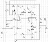
I had a bit of a play with the topology that we ended up with in the guitar preamp thread. I added a stage, and increased Iq for the amplifier to about 12mA (with +/-15V supplies).
With gain set to 20dB (It's not unity stable) I get 0.0004%THD (20Vpp into 1K), and 0.00004%THD (2Vpp into 1K).
I think that's fairly reasonable for 11 transistors...
Cheers,
Suzy
An externally hosted image should be here but it was not working when we last tested it.
With gain set to 20dB (It's not unity stable) I get 0.0004%THD (20Vpp into 1K), and 0.00004%THD (2Vpp into 1K).
I think that's fairly reasonable for 11 transistors...
Cheers,
Suzy
G.Kleinschmidt said:THD results 20Hz-20kHz = 0.000%.
I need a SPICE simulator with better resolution!
LTspice does six decimal places...
Cheers,
Suzy
suzyj said:
LTspice does six decimal places...
Cheers,
Suzy
Currently downloading LTspice......This is painfull on dialup internet access.....
Cheers,
Glen
Hi Glen,
When doing a sim of distortion in LTSpice, you'll need to add the SPICE directive ".options plotwinsize=0" without quotes. This will disable data compression, which messes with distortion accuracy. This can be disabled via the Control Panel, but on the next invocation of the program, LTSpice will set it back to the default of compression. ".options plotwinsize=0" will always force compression off. When you add a ".four" directive, you'll need to do a "View, SPICE error log" to see the THD results after transient sim. LTSpice is kind of a PITA in this regard, but the price is right.
When doing a sim of distortion in LTSpice, you'll need to add the SPICE directive ".options plotwinsize=0" without quotes. This will disable data compression, which messes with distortion accuracy. This can be disabled via the Control Panel, but on the next invocation of the program, LTSpice will set it back to the default of compression. ".options plotwinsize=0" will always force compression off. When you add a ".four" directive, you'll need to do a "View, SPICE error log" to see the THD results after transient sim. LTSpice is kind of a PITA in this regard, but the price is right.
A second try with compensation that doesn't destroy the slew rate:
0.00002% THD (1KHz 20vpp into 1KOhm)
0.000001% THD (1KHz 2Vpp into 1KOhm)
0.001% THD (10KHz 20Vpp into 1KOhm)
0.00008% THD (10KHz 2Vpp into 1KOhm)
It's still slew rate limiting a little at 10KHz 20Vpp...
Cheers,
Suzy
An externally hosted image should be here but it was not working when we last tested it.
0.00002% THD (1KHz 20vpp into 1KOhm)
0.000001% THD (1KHz 2Vpp into 1KOhm)
0.001% THD (10KHz 20Vpp into 1KOhm)
0.00008% THD (10KHz 2Vpp into 1KOhm)
It's still slew rate limiting a little at 10KHz 20Vpp...
Cheers,
Suzy
Re: Lineup Standard OP-Amp circuit schematic
Wavebourn
I am sorry, but I am quite new using my spice. EWB MultiSim9.
So what tests I have learned and can do now is:
- Function Generator input, sinus triangle, square waves.
- Distortion Analyzer of sinus waves.
- Oscilloscope looking at output
- AC Analyse, giving frequency bandwidth curves
- Fourier Analyse, for harmonics
--- to manage good with other tests I need some guidance.
So unity gain f and slew rate, no I do not know.
I do not even know exactly what you mean with unity gain frequency.
Slewrate I know about what it is.
But I know that the first stable prototype
was having a way too high upper
upper limit: > 10 MHz
As you can see:
1st stage: gain 2000/200 ~10
2nd stage: maximal
The prototype I am talking about, was using a limiting filter , for reducing AC gain.
For example 2.2uF - 20000 ohm in series was used first,
from output transistors bases , to V-, negative supply rails.
I am a great fan of limited total AC gain (using local feedback degeneration resistance)
I have always been!
And now I am able to see what good effect this have, in my simulation measured data.
============================================
I really believe in addition options, feature for people
to set custom wanted AC gain.
If I produced a 'standard discrete op-amp'
I would add instructions and simple possibility for anybody
to set
- the Constant current in each stage
- the AC gain in each stage
... this way we can control linearity, speed and the amount of global feedback
... at various closed loop gains.
And quickly optimize each Discrete OP,
to various sources, loads and bandwidths.
============================================
My target was for this op-amp, to limit open loop AC gain to something like 1000.
This is very very low in compare of most Chips OP-Amplifiers out there!
1st stage: Gain 2000/200 ~10
2nd stage: Gain 20000/200 ~100
Total GAIN: ~10x100 ..... <1000
It turned out when testing, that the optimal gain of second stage
for one special testing was:
9300 ohm / 200 ohm ~46.5
Giving only 465 total AC gain.
... I am quite sure this was for UNITY GAIN, buffer, testing.

Lineup Audio OP Amplifiers Co.
.. at work in testing ..
http://lineup.awardspace.com/
***************************
Notice, like Rod ESP Elliott in some projects, I want ONLY to use 'easy values' of components.
Only a few values, that you could buy 100 of (lower price) and always have at home
... like 100, 1k, 10k, 100k, 220, 2k2, 22k, 470, 4k7 47k
if you see 200, 2000, it could mean
two resistors in series: 100+100, 1k+1k.
As well as could mean 220, 2k2
The reason I am using 200 and NOT 220 in first schematics
is only because of easy calculting.
Because I do most of my math, using only my own head, when designing.
This is for to make it more easy for myself.
For such a STANDARD discrete Op-amp, final version,
I would see it is a FAILURE
if I had to any other value, except:
10, 22, 47 (E3)
Same goes of course for capacitors:
22pF 47pF 100pF, 220pF,
470pF 1uF 2.2uF 4.7uF
ONLY 3 values
1 and 2.2 and 4.7
and multiples of those.
Wavebourn said:
What is unity gain frequency and slew rate?
It seems to be fast and low noisy.
Wavebourn
I am sorry, but I am quite new using my spice. EWB MultiSim9.
So what tests I have learned and can do now is:
- Function Generator input, sinus triangle, square waves.
- Distortion Analyzer of sinus waves.
- Oscilloscope looking at output
- AC Analyse, giving frequency bandwidth curves
- Fourier Analyse, for harmonics
--- to manage good with other tests I need some guidance.
So unity gain f and slew rate, no I do not know.
I do not even know exactly what you mean with unity gain frequency.
Slewrate I know about what it is.
But I know that the first stable prototype
was having a way too high upper
upper limit: > 10 MHz
As you can see:
1st stage: gain 2000/200 ~10
2nd stage: maximal
The prototype I am talking about, was using a limiting filter , for reducing AC gain.
For example 2.2uF - 20000 ohm in series was used first,
from output transistors bases , to V-, negative supply rails.
I am a great fan of limited total AC gain (using local feedback degeneration resistance)
I have always been!
And now I am able to see what good effect this have, in my simulation measured data.
============================================
I really believe in addition options, feature for people
to set custom wanted AC gain.
If I produced a 'standard discrete op-amp'
I would add instructions and simple possibility for anybody
to set
- the Constant current in each stage
- the AC gain in each stage
... this way we can control linearity, speed and the amount of global feedback
... at various closed loop gains.
And quickly optimize each Discrete OP,
to various sources, loads and bandwidths.
============================================
My target was for this op-amp, to limit open loop AC gain to something like 1000.
This is very very low in compare of most Chips OP-Amplifiers out there!
1st stage: Gain 2000/200 ~10
2nd stage: Gain 20000/200 ~100
Total GAIN: ~10x100 ..... <1000
It turned out when testing, that the optimal gain of second stage
for one special testing was:
9300 ohm / 200 ohm ~46.5
Giving only 465 total AC gain.
... I am quite sure this was for UNITY GAIN, buffer, testing.
Lineup Audio OP Amplifiers Co.
.. at work in testing ..
http://lineup.awardspace.com/
***************************
Notice, like Rod ESP Elliott in some projects, I want ONLY to use 'easy values' of components.
Only a few values, that you could buy 100 of (lower price) and always have at home
... like 100, 1k, 10k, 100k, 220, 2k2, 22k, 470, 4k7 47k
if you see 200, 2000, it could mean
two resistors in series: 100+100, 1k+1k.
As well as could mean 220, 2k2
The reason I am using 200 and NOT 220 in first schematics
is only because of easy calculting.
Because I do most of my math, using only my own head, when designing.
This is for to make it more easy for myself.
For such a STANDARD discrete Op-amp, final version,
I would see it is a FAILURE
if I had to any other value, except:
10, 22, 47 (E3)
Same goes of course for capacitors:
22pF 47pF 100pF, 220pF,
470pF 1uF 2.2uF 4.7uF
ONLY 3 values
1 and 2.2 and 4.7
and multiples of those.
Attachments
Re: Re: Lineup Standard OP-Amp circuit schematic
Slew rate is simply how quickly the output of the amplifier can change voltage.
If you put a step in (square wave), the amplifiers output will be a ramp. The slew rate is simply the rate of change of voltage of this ramp, and is usually quoted in V/us. Amplifiers that are "slew rate limited" are simply not able to change the voltage at the output fast enough to keep pace with the music. Sine waves turn into triangles under severe slew rate limiting, and leads to poor intermodulation performance.
Typical IC audio opamps have slew rates in the neighbourhood of 1-10 V/us.
Unity gain frequency is simply the frequency at which the open-loop amplifiers gain drops to zero dB. It's observed simply by doing an AC sim, and looking at V(out)/V(in). You'll also see basically the same thing quoted as "Gain bandwidth product".
A typical audio opamp will have a unity gain frequency of a MHz or better.
Cheers,
Suzy
lineup said:So unity gain f and slew rate, no I do not know.
I do not even know exactly what you mean with unity gain frequency.
Slewrate I know about what it is.
Slew rate is simply how quickly the output of the amplifier can change voltage.
If you put a step in (square wave), the amplifiers output will be a ramp. The slew rate is simply the rate of change of voltage of this ramp, and is usually quoted in V/us. Amplifiers that are "slew rate limited" are simply not able to change the voltage at the output fast enough to keep pace with the music. Sine waves turn into triangles under severe slew rate limiting, and leads to poor intermodulation performance.
Typical IC audio opamps have slew rates in the neighbourhood of 1-10 V/us.
Unity gain frequency is simply the frequency at which the open-loop amplifiers gain drops to zero dB. It's observed simply by doing an AC sim, and looking at V(out)/V(in). You'll also see basically the same thing quoted as "Gain bandwidth product".
A typical audio opamp will have a unity gain frequency of a MHz or better.
Cheers,
Suzy
G.Kleinschmidt said:
An externally hosted image should be here but it was not working when we last tested it.
Cheers,
Glen
After a long time, the circuit that is very interesting from my point of view. Congratulations, Glen.
Cheers,
Pavel
andy_c said:Hi Glen,
When doing a sim of distortion in LTSpice, you'll need to add the SPICE directive ".options plotwinsize=0" without quotes. This will disable data compression, which messes with distortion accuracy. This can be disabled via the Control Panel, but on the next invocation of the program, LTSpice will set it back to the default of compression. ".options plotwinsize=0" will always force compression off. When you add a ".four" directive, you'll need to do a "View, SPICE error log" to see the THD results after transient sim. LTSpice is kind of a PITA in this regard, but the price is right.
Thanks alot for the pointer. That probably would have taken a bit of effort to figure out!
Cheers,
Glen
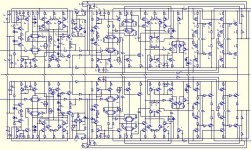
G.Kleinschmidt said:Now I can begin laying out the PCB.......
110 bipolar transistors and 12 dual jfets!......
G.Kleinschmidt said:Preliminary schematic MKII
Upupa Epops said:VERY NICE, Glen, I like complicated circuits

... pcb for 110 bjt + 12 dual fet
good lucki like complicated circuits

If you do and it works for you, good
So from this I get, that Upupa 'surpuppa' Epops
wouldn't use one amplifier chip, to design his amplifier construction
it would be too simple
Myself, lineup, as most everybody knows
is a bit different from such complications
and like in this, however interesting and certainly ABSOLUTELY high performance, circuit
i find, still today,
by
keep it simple & good
does not make me miss much of any audio recording
even compared to using complicated/space technology/advanced constructions
Regards to hard working
friend G.Kleinschmidt
from
______________________________________
lineup
Lineup Good & Sound Audio Designs
at
http://lineup.awardspace.com/
Upupa Epops said:VERY NICE, Glen, I like complicated circuits....
Me too!
lineup said:
... pcb for 110 bjt + 12 dual fet
It's really not that bad. A double sided SMD board with SOT-23 and SOT-223 transistors (the bottom layer power rail and grounding plane, top layer signal plane) really is a piece of cake to layout. I wouldn’t contemplate homebrewing this design with through-hole components though – too many holes to drill!
Cheers,
Glen
- Status
- This old topic is closed. If you want to reopen this topic, contact a moderator using the "Report Post" button.
- Home
- Amplifiers
- Solid State
- Super preamp.