Interesting, did you remove the series connected VAS in your sim version of the Super Amp?
It is a bit crazy IMO to take the 1/2 Vout reference from the output stage splitter, there are simpler ways to do it, but I'd just remove it and use a device with enough SOA.
I think it might be the way to go, and even also remove the stacked devices from the predrivers, and even the drivers themselves. Keeping only the power output devices stacked, which is the main purpose, to enable using the low Vce0 3055 instead.
But I'm not so sure about how to alter that topo so profoundly. I don't see how to properly interface a non stacked predriver/driver stage with the stacked output stage.
Only the 3055s are demanding the help for their Vce0 issue. Everything else, except the front end though, doesn't require the stacking.
The front end should remain cascoded. That's one important leach thing.
The whole point was to make a 3055 based super leach amp, which I believe can be done. Now it just has to be made stable and reliable.
While trying to figure out a way to get this damn protection to work properly. That is to make it work as it would be calculated, with the end result being exactly what the calculations say would happen, which is to limit the excursion and keep it within the SOA. I ended up adding one more "set" of devices, for a total of 16 outputs (3055s+2955s).
And that would allow it to be fairly well protected, although not 100%, but close, from getting out of SOA on a dead short.
But 16 TO3s, that's a whole lot of heatsink real estate. Even though it wouldn't dissipate more, the area where the devices are bolted on the sink would have to be sufficient.
Just for kicks, and to think ahead a bit, I looked again at one of conrad heatsink's nice design, the 30cm long version of their single flanged sink.
I have it drawn in cad, along with the TO3 cases, so I could slap on as many as possible of them in there, and only 10 such devices could realistically fit in such a space (30cm/~12in).
Obviously if someone wanted to make this 16 device version of the amp, it would take more heatsink space to hold them. For example maybe 2 of their 20cm long ones, with half the devices on each. But then the thermal sensing would require some tweaking, with 2 sensing devices.
That brings me to one beef that I do have against leach's design: the thermal sensing using diodes. I really can't stand that. I just don't want to screw around with extra wires and boring more small holes to pass diodes through a heatsink.
Not good.
I would rework the thermal sensing for 2 devices, with TO126 devices, not some diodes or TO92 that are too difficult to get in good enough contact with the sinks, and no wiring, just bolt and solder parts on a pcb.
I'm a diyer and perfer easier simple approach.
The Leach amps have nested loops that interact, so I'm not sure that you applied the TIAN probe properly. I'd try the simpler method in the LTspice examples.
That's quite possible, but I don't think placing a different type of probe would make it any easier. The difficulty is where to insert the probe.
What I did is place the probe right at the output bus, before the LR output and zobel network, and placed the feebback pickups right there after the probe, keeping it inside the loop.
Of course the inner small local miller loop just can't be looked at this way, and there is no easy way, that I could find, to place it to include the nested loop that picks up the center of the pre-drivers.
You claim that the feedback loops must be balanced or matched?
Actually, it's not really me. I am just forwarding what an other forum guru had explained before about this. He didn't give enough detailed explanations so I could understand it and calculate it, but he was clearly saying those 2 loops do have the same corner frequency.
I suggest that you try what I suggested on R20, but first it would probably be better to have a few more eyes look at your sim for an error since it does not make sense.
Probably. I've gone through so many variations, I need to make different versions and keep a clean one that reflects the original only.
First, I'd remove the series connected VAS it was there due to limitations of the time.
That part shouldn't be much trouble, but removing the stacking from what follows is much more involved.
There is feedback in the drive for the series connected parts that might cause issues. You might have local stability issues that are typically solved with base stoppers or caps.
That's one thing I did explore, although without serious topo alterations.
I added caps on the BC of the Q26 and Q27, and also caps from C to ground on Q16 and Q17 (the stacked drivers).
Also added caps on R21+R23 and R22+R24. Small values, but it did help some.
But only after I removed the nested loops and replaced them by TMC with those other mods, with the right models, and the 3055s replaced by cordell's MJL21193/4, did it become stable enough.
Actually, after all those mods, the tian probe could report a phase margin in the order of 65degrees, depending on cap values...
I simulated the Bryson BTW, and there is a reverse Vbe issue on one of the drivers.
Me too, many variants of theirs, but not yet much thermal wise. A I do want to look into this as well, and get a good grip on it, as I am thinking of using this kind of topo for my big 4 way active project.
I need to get a handle on how their compensation works and how to make it work best and properly implement it in a build.
But this is an other subject that belongs in an other thread really.
If you post your .asc I'll look it over and suggest a mod to remove the series parts that need to go, not the outputs.
Alright, we can do that. For the 3055 based version, I have it altered quite a bit, with the mods I mentioned earlier.
The sim requires a bit of cleanup of some bits and pieces for my sim use, and then I need to gather the models to make up a single zip. I'll take a look tomorrow.
There is a Heathkit version of the amp, have you seen a schematic?
No. Actually I never heard of such a heathkit version. Were they sold at radioshack or something like that? (is radioshack still alive?)
No I don't think they were sold at RS, RS is going up for their second bankruptcy, not sure
what the outcome will be. I'll look for the Heathkit schematic.
There were also versions manufactured by a few companies, two associated with Leach,
they are mentioned here:
https://leachlegacy.ece.gatech.edu/lsrd/index.html
Here is a .pdf of schematics for designs from one of the companies, there are comments
from Leach at the end, some about oscillations:
https://leachlegacy.ece.gatech.edu/lsrd/electronicsone.pdf
There are many Leach experts on this forum, have any of them commented about your work?
I am not one of them by the way.
Thread on the Heathkit AA-1800 done by one of Leach's students:
http://www.diyaudio.com/forums/solid-state/1948-heathkit-amp-preamp.html
Schematic, note that the series connected VAS is gone, the series connected output is CFP
(Q123,Q124) on the driver, and he uses MIC HF compensation - you might have to login at CSP to see it:
http://www.classicspeakerpages.net/IP.Board/uploads/post-100682-1185488054.jpg
Last edited:
yes, there was a leach superamp redesign thread here years back....
here is the google listing.....https://www.google.com.ph/search?q=...amp+redesign+diyaudio+site:www.diyaudio.com&*
here is the google listing.....https://www.google.com.ph/search?q=...amp+redesign+diyaudio+site:www.diyaudio.com&*
yes, there was a leach superamp redesign thread here years back....
here is the google listing.....https://www.google.com.ph/search?q=...amp+redesign+diyaudio+site:www.diyaudio.com&*
Is there info on stability improvements or analysis?
No I don't think they were sold at RS, RS is going up for their second bankruptcy, not sure what the outcome will be.
Well, they never seemed to be any good anyway. They're totally unknown in europe, and I don't think it matters if they disappeared, they wouldn't be missed. They had an overly limited choice in the electronics parts area and they were much too pricey.
They ventured into the computer market for a while with their Tandy and whatever, but that was just a phase. I owned an old PC long ago that was a heathkit.
There were also versions manufactured by a few companies, two associated with Leach,
they are mentioned here:
https://leachlegacy.ece.gatech.edu/lsrd/index.html
Here is a .pdf of schematics for designs from one of the companies, there are comments
from Leach at the end, some about oscillations:
https://leachlegacy.ece.gatech.edu/lsrd/electronicsone.pdf
Those companies were very ephemeral and didn't have much impact.
There are many Leach experts on this forum, have any of them commented about your work?
Not so far. And one of them who did a nifty pcb job (Jens) has apparently totally lost interest and hasn't been participating much for quite some time.
A superleach redesign was in the works, and there was interest, but it's fallen into oblivion since.
Heathkit AA-1800 schematic attached, posting it here in case you can't read it at CSP:
100V rails are insane.
Definitely insane and not for 3055s.
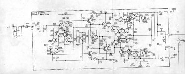
It's not much of a leach though, the front end is nothing like leach's, it's just a standard fully symmetric ltp with nothing special, seen everywhere out there. Not a specific low tim design.
I find it a bit hard to understand in the way the output stage is drawn.
What are those part numbers corresponding to?
I'm not too sure about that offset adjustment system. Wouldn't that be exposing the coupling cap there to extra dc?
One other odd thing is the bias trimmer. What happens if the cursor lifted?
I don't even see the purpose of the additional fuses for the front end.
What are those diodes D103/4 for?
Curious how a nested feedback loop picks up at the base of Q112, only on one side (nothing on Q111).
There are quite a few caps also sprinkled all over, which shows there may be the same kind of instabilities to fight against.
At least one thing is done right, the freewheeling diodes are actually connected on the amp's output and not on the speaker side of the output LR.
Could be educational to simulate though.
One thing I am curious about is the thermal feedback scheme for all amps. I'd like to get a deeper understanding of those. The leach amp with its 4 diodes has those 4 junctions in series to multiply by 4 the drift, while most amps only use a single transistor, which should have only one junction drift...
How to make the bias spreader compensate the exact amount of drift according to the output stage topo? What needs to be different in the bias spreader for a 2EF, 3EF, etc...
I've been doing some thermal analysis recently, on a grounded collector design, still ongoing. And that revealed quite a bit of info.
Here it is. Hopefully no missing models if executed out of the box.
It's the version before I started making more changes like removing the inner feedback loops and switched to tmc.
Very few things changed compared to the original.
I did move the freewheeling diodes to the amp's side and the zobel as well.
The models for the 3055s are pointing to slightly tweaked ones, with VAF adjusted.
I think instead of completely removing the stacked vas tranny, it should be better if converted into a real cascode, perhaps a hawksford type, which was one of the things I was thinking about doing.
Not only it still would be a plus to have the vas cascoded, but the added isolation of the vas from the output stages would be good to have.
In some of the versions I made along the way, making some changes, I did increase the vas bias current somewhat. And I tried adding baker clamps (BAT54) on the vas, hoping to prevent the nasty sticking behavior happening at clipping.
Attachments
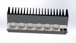
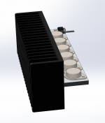
Here are a couple of visuals for a possible arrangement of heatsink, which would work with the conrad MF20 single flanged sinks.
In such a 20cm length, we can fit 6 TO3s, along with a TO220 driver and a TO126 sensor. And it fits just right.
There would be 2 of such arrangements required for a superamp with 3 sets, as long as it's been scaled down to only the outputs stacked, the other stacked devices having been removed from the design.
This could be set up as a single long sink by bolting 2 of them together to make a single 40cm long one, or the pcb could be designed in a way to have each sink on its own side, making the amp more compact.
I was already looking at such an arrangement for a 3055 based grounded bridge amp.
One other thing could be done, to make the thermal coupling even better for the TO126 sensor: slapping that TO126 sensor right on one of the TO3s, bolted with a common screw. This would probably require a little bit of preparation on the TO3 device, depending on how it's made, by filing a tiny bit of the round part of the case to allow the TO126 to sit nicely in its space, and of course an insulator would be required to separate the TO3 and TO126, but that would make a single thermal junction instead of 2, for the thermal link between them, and much less thermal lag.
Attachments
The Leach superamp was invented to cope with a problem that existed at that time.
The problem:
most complementary output devices at that time, had an SOA and Vce0 that limited the maximum output voltage and their application to lower power amplifiers.
Today we have dozens of complementary output devices that have a high SOA and a high Vceo. The need for the cascade of output devices has virtually disappeared.
We see the newer implementation in Class G & H amplifiers where the cascading is switched On as high voltage becomes necessary for PA duty and their kW outputs.
Today we have devices that can easily achieve 300W into 8ohms without any fancy cascades to lower the applied voltages.
The Leach Lo Tim could very easily be scaled using modern devices to meet 300W into 8ohms.
Last edited:
The Leach superamp was invented to cope with a problem that existed at that time.
The problem:
most complementary output devices at that time, had an SOA and Vce0 that limited the maximum output voltage and their application to lower power amplifiers.
Exactly! And that's why it's justified for those wanting to make use of the older devices that required this.
Today we have dozens of complementary output devices that have a high SOA and a high Vceo. The need for the cascade of output devices has virtually disappeared.
Totally! No need with those new devices, but still for the older ones, and many of us still have those in old new stock. And besides, in some parts of the world, those older devices are easier and cheaper to get.
We see the newer implementation in Class G & H amplifiers where the cascading is switched On as high voltage becomes necessary for PA duty and their kW outputs.
And those make for truly beasty amps, but for diyers, not so much an easy thing to tackle. And besides, those amps do suffer from some issues that reduce performance compared to other topos.
I doubt the class G and H will ever be able to rival the class a, and likely not even the best AB.
Today we have devices that can easily achieve 300W into 8ohms without any fancy cascades to lower the applied voltages.
That's true. But not for the older devices.
The Leach Lo Tim could very easily be scaled using modern devices to meet 300W into 8ohms.
And that's been done over and over. And some went even higher.
Hello, I am followed with interest to your activity")
btw now I listen to music through classical Low Tim - one of my favorite amp.
in terms of complexity of mounting thermal sensing diode: I soldered them on a separate small PCB and then i grind them flat and then screw them on heat sink between transistors using thermal grease. Works fine.
btw now I listen to music through classical Low Tim - one of my favorite amp.
in terms of complexity of mounting thermal sensing diode: I soldered them on a separate small PCB and then i grind them flat and then screw them on heat sink between transistors using thermal grease. Works fine.
Attachments
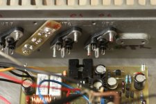
in terms of complexity of mounting thermal sensing diode: I soldered them on a separate small PCB and then i grind them flat and then screw them on heat sink between transistors using thermal grease. Works fine.
It can always be made to work somehow, but what a pain to do. Extra wiring, more stuff to be more likely to fail over time. Plus the grinding of plastic may seem like it would work fine for a better contact, it's still not going to be as good as a properly bolted case on a sink.
I'm certainly not saying it can't be done, I just am not liking that method. I prefer something less flimsy.
Now I'm looking into various bias spreader topos right now, simulating, comparing, and trying to get a better grasp of how they work and how to properly choose the right type for each application.
I've done some tests already on the grounded collector design, which apparently isn't overly prone to thermal runaways, but haven't found the best spreader yet that can keep the bias as constant as possible. Still looking.
The reason why I pointed out the Heathkit is that it might have solved some, if any, of the
stability issues that you are seeing. It is another opinion, with a series output stage and a
normal VAS as I suggested.
Yes, it has less diff pair degeneration, and much more on the VAS, it has Miller Inclusive
HF feedback which Bob C. seems to like.
I'm surprised that you are so quick to dismiss the manufactured Leachs; when you build a
lot of them you find more issues. It sounds like the notes about mods are from Leach
himself.
You seem to have a high opinion of these designs, are you aware of Bob C.'s "Another View
of TIM"? And the war that started over the validity of TIM? Andy_c took Leach's audio
Eng class and talked about how Leach's views changed over time, this was no secret he
kept issuing revisions of the Low TIM amp.
Your sim is missing the 1N4004 model, no big deal obviously.
Was there a particularly good case that demonstrates the instability?
This is my basic view of thermal compensation.
Obviously the goal is to compensate the Vbe tempco so that the idle bias remains constant.
Count the number of junctions on devices that get hot from one VAS out to the other.
There are 6 in the Leach and so it seems that he is not compensating for the pre-driver.
Seems that 2 of those sense diodes should go on the drivers, and two on the outputs,
but most just put them on the outputs probably on the idea that they heat up the most and
if the drivers begin to run away then the outputs will heat more also.
Vbe multipliers use the gain of the transistor, obviously, to multiply one diode drop to
however many junctions need to be compensated. The "diode" can be the Vbe of the
transistor itself.
- Status
- This old topic is closed. If you want to reopen this topic, contact a moderator using the "Report Post" button.
- Home
- Amplifiers
- Solid State
- Super Leach amp simulation woes