The Superamp with lots of part count and a not so simple schematic would be easy to get wrong in simulation (build too) so my advise is to check connections very carefully.
Definitely! Not an easy DIY build.
But with a PCB design made to minimize cabling and number of boards, the complexity can be made much less apparent and reduce possible mistakes a lot.
It's all in the layout, and with the cabling at a minimum, the ground loop and such mistakes could be kept down.
Go to Leach site in the original (not superamp) amp, there is LTspice file. I tried it and it worked. You can start with this and slowly add the cascodes, test every cascode pair added and save then continue until output transistors.
Already done that, long ago. And found the simulated leach amp doesn't show as very good performance, with high distortion. Perhaps it's mostly the models. But I suspect the low open loop gain scheme and some lower level of linearities somewhere must be making it difficult to reduce thd. The main goal of the design was to eliminate the nasty TIM, which is probably why the amp sounds great even though the thd is higher than other amps, as tim must be harsher on the ears than thd.
My idea about a build is to eliminate as much wiring as possible, on a single PCB, which would include everything but the power transformer, so it would have very few wires to connect. Only the power transformer's wires would go to the PCB, and then everything else on that PCB, even the input plugs and whatever is used for output connection if possible.
Only this would make for an easy DIY build, that could work right out of the box and eliminate as many possibilities for mistakes as possible.
The devices should of course be matched beforehand as much as possible, including the critical parts like resistors for the front end, and others.
It really isn't that much more to do to test parts and match them.
When I can get this sim to work right, it'll need some cleanup work for sharing, but I can then post it here for others to play with.
A good PCB design could be started on this then.
I'm wondering something: let's say I swap the output device models to use the MJ21193/4 from Cordell, which aren't causing the big oscillation issue, if the other models are also working right, then would this really be that different from the 3055s?
I mean what if all the sims are made with those MJs, but assuming it would work about the same with the 3055, would that still be ok?!?
I got it to work that way now, using the 2SA1381/2SC3503 for vas and its cascode, and the pre-drivers and their stacked brethren, the MJE15030/1 (not cordell's) for the drivers, and the MJL21193/4 instead of the 3055s (Cordell's).
I also changed the whole compensation scheme, with TMC, plus caps on the vas and on all drivers, to stop oscillations.
A few values altered, for example I upped the vas bias current somewhat and pushed down the trigger point on the vas limiter, which wasn't even acting at all on shorts, although the vas was pumping out about 13mA (shorted/sunk by the protection circuit).
The output base stoppers at 4.7ohms, the emitter res at 0.22.
Also I lowered the values on the degen res and base stoppers on the front end, to 130ohms for the degen and 100 for the base res.
I added a protection circuit as a VI dual slope as described by Kiwanuka, but calculated values don't give the exact results they should, and the protection is either way too intrusive so it can attempt to keep things in the SOA, or they don't act enough and we're way out of SOA. The protection trannies are much too progressive and start acting far too early, so they cause a lot of distortion. If we calculate to push back the threshold to make it less intrusive, then protection happens too late and we're out of SOA.
It may sound nice and near on paper with those calculations, and it's supposed to be possible to make it effective while keeping it un-intrusive, but reality just ain't that way.
There is plenty of spare SOA even under 2ohms (resistive load) with 3 sets of outputs, but once we push that into a dead short, things get all out of hands, with phase shifts between current and voltage, so the protection circuit does act to keep both the current and voltage very well within the limits, but since they're out of phase, the dissipation is too high on peaks and it can go out of SOA regardless.
I would really like to see other's simulation results on protections, because I just do see them being feasible to be properly set for exact results as intended.
Did you derate the outputs for heatsink temp rise, say assuming 75 deg C case temp?
Yes. See attached example.
Yes, since they aren't "pairs", I just call them "sets", because there are 4 per set, 2 of each NPN/PNP, and this simulation is done with 3 sets, for 6 NPNs and 6 PNPs.When you say 3 sets of outputs, I assume you mean series connected for a total of 6 output devices per channel?
I'm cleaning it up, so it can be posted here later on.
Attachments
By the way, as I mentioned earlier. Although that sim shows the 3055/2955 being used, I swapped those models for Cordell's MJL21193/4 to make it work this way. The voltages and current measured from the working circuit would be the same as far as delivering power to the load, so the plotted curves for the SOA usage would be like those for the 3055s.
and this simulation is done with 3 sets, for 6 NPNs and 6 PNPs.
So 12 output devices per channel, just to be sure I'm following?
So 12 output devices per channel, just to be sure I'm following?
Yes, that what I meant by the 6+6. (6 x 3055 + 6 x 2955). One set = 4 devices instead of the 2 in conventional pushpull.
Rails being twice as high as they would be in a regular pushpull, power more than simply doubles, in theory it would quadruple, but the stacking causes some extra overhead losses.
And I've been thinking it would be better to have a slightly higher regulated and quiet voltage for the front end, like 65V or maybe a bit more. This would not only compensate for the extra overhead in the cascodes, so it would drive the outputs a little further, it would also be more quiet with a good regulation.
The leach superamp isn't an easy build, and it's not really just due to the extra complexity from a higher part count.
Just like the regular leach amp, one bad thing is using those diodes to sense the heatsink. This really is a rigging job and having to drill through the heatsink for those things and wire them really makes for an unpleasant build, not to mention the extra wiring lengths and what that brings.
The TO3s are a bit more limiting to make it easy to build than the TO264s or TO247s, but there are ways to make this less painful to assemble and wire by choosing the right heatsink profile.
I like the clean and neat builds with very little wiring and as few as possible pcbs.
I've learned over the years that perhaps it is better not to take the outputs so deep into saturation, they tend to stick and have trouble coming out leading to cross conduction.
That may be true, and it's probably better to clip on the vas rather than the outputs, but I think there is some headroom in this one, with the cascode on the vas for one. It might not hurt to have the front end's rails a bit higher, like 5V perhaps, and even if not higher, at least on its own regulated supply, not just a ripple eater from the main rails.
One thing I can see in this superamp sim, is the clipping is rather ugly, and I'm not even certain yet where it does clip. But it shows some sticking, which I couldn't cure with baker clamps (bav21 on the vas), and there are some oscillations as well. Not a clean and well behaved clipping behavior.
I find it odd that such a proven design would require more work to make it work properly.
Maybe it's just the simulation and this doesn't happen on a real build, but it's odd that it happens on this amp and not on others with the same models.
The fact that you are using 12 output devices just sunk in, there is going to be
a lot of capacitance involved there and "slowness" through the output stage.
Let me guess you already tried lowering the number of output devices?
I would lower the supply voltage to something like +/- 40, reduce it to one or
two pairs of outputs, and see if you can get a basic Leach amp to work with
those outputs.
It is interesting that the compensation in the Leach amp rolls off HF from the slow
main output and takes the HF from the first EF through a small cap which should
make it less sensitive to output device speed - perhaps Leach overlooked something.
The fact that you are using 12 output devices just sunk in, there is going to be a lot of capacitance involved there and "slowness" through the output stage.
Let me guess you already tried lowering the number of output devices?
Of course, and I actually tried the leach amp as is before, with 3055s and lower rails. The regular leach amp simulates properly, although with not so good performances.
The issue with the superamp is that it doesn't simulate well at all, and only after going through a big sample of various models, it finally worked (kind of), and still with performance that are really marginal. It's prone to oscillations and they show up when non-normal conditions are brought up, like overly hard load or dead short.
I would lower the supply voltage to something like +/- 40, reduce it to one or two pairs of outputs, and see if you can get a basic Leach amp to work with those outputs.
I did that, and the main issue is with the superamp, which is much harder to get to work properly.
It is interesting that the compensation in the Leach amp rolls off HF from the slow main output and takes the HF from the first EF through a small cap which should make it less sensitive to output device speed - perhaps Leach overlooked something.
Quite possible, and I think he didn't make much use of the simulators to verify his calculations.
Obviously his designs did work fine, with the huge number of amps built, but I suspect those could've been even much better if fully simulated to iron out the remaining oddities.
I tried the superamp with front end rails at higher and lower voltages than the power rails, just to find out for sure where it clips first.
Apparently, as far as I can see, it's not the vas that clips but indeed the output stages, and the clipping behavior isn't pretty at all, with some amount of sticking, and oscillations showing up, as well as some artifacts of what looks like crossover issues.
One other thing I found out is the vas current looks like there is a huge amount of cross over problem. Even with my increasing the vas bias current to about 5mA, it's not giving out a sine wave. The feedback loops force a correction that makes most of those huge issues disappear, so we get a sine wave on the output, but although the sine looks fine visually, the thd doesn't lie and shows an overly high amount, like sometimes much more than 4%, depending on loading and frequency.
At 1khz it's not too bad, but at 20khz it really begs for improvements.
My attempts at the moment are to make a 3055 based version, but this doesn't prevent it from being used with whatever outputs we want. Once it's made to work right, devices can be chosen appropriately, along with the rail voltages and the values for the VI limiters.
The thing is, just like I've seen it in most simulations, although the VI limiters do act and effect a real fold back, that foldback isn't quite enough to keep things within the soa in extreme conditions.
The other bad thing about the limiters is that because they act in an overly progressive manner, they intrude in the proper function when in the valid signal and load levels, so the only way to make this viable is to add more output devices (which adds even more capacitance). So we must have more output device sets than really should be sufficient, just because the limiters act too progressively.
I just used the regular leach amp simulation as was posted on leach's site, with only a few adjustments to the spice directives to test various things.
Used the models that came with that sim, the outputs being the MJ15003/4 and the drivers MJE15030/1.
Those models don't allow the superamp sim to work, as I mentioned before.
I kept the same part numbering and the original values for the leach amp.
What I was curious about was how the VI limiters work, and as I expected, they just don't do what they're supposed to do. At least not to the extent they are supposed to, which is to prevent SOA violations.
That amp was made to be able to handle 8 and 4ohms loads, so if we want to cover all angles, for the worst case reactive load situation, we load it at 2ohms resistive, and there at full nominal drive level for full power, the VI limiters do act, and they are not really preventing the SOA violation, if we take a derated SOA for 75C case temperature, which would be a maximum really.
So in fact, at 2ohms and full power, which would be on a worst reactive load of 4ohms nominal, the limiters are intrusive, and yet don't truly protect the amp if it's hot to the max.
The worst part is if we throw a crowbar on its output. I put a 1mohm dead short on the load, and the SOA is totally violated, the limiter are not preventing a potential failure.
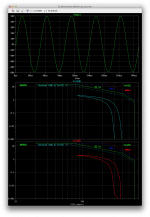
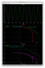
As an example, I'm posting a visual of the 2ohms resistive load case, where we can see the derated SOA being slightly violated for the outputs (just one of them, as they are all dissipating about the same).
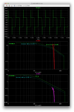
The next posted visual is this same sim but with a 1mohm dead short on the load, and it's quite clear how the limiters just can't keep it SOA safe.
One good thing at least is that although the outputs have their SOA grossly violated, the drivers are safe there.
Used the models that came with that sim, the outputs being the MJ15003/4 and the drivers MJE15030/1.
Those models don't allow the superamp sim to work, as I mentioned before.
I kept the same part numbering and the original values for the leach amp.
What I was curious about was how the VI limiters work, and as I expected, they just don't do what they're supposed to do. At least not to the extent they are supposed to, which is to prevent SOA violations.
That amp was made to be able to handle 8 and 4ohms loads, so if we want to cover all angles, for the worst case reactive load situation, we load it at 2ohms resistive, and there at full nominal drive level for full power, the VI limiters do act, and they are not really preventing the SOA violation, if we take a derated SOA for 75C case temperature, which would be a maximum really.
So in fact, at 2ohms and full power, which would be on a worst reactive load of 4ohms nominal, the limiters are intrusive, and yet don't truly protect the amp if it's hot to the max.
The worst part is if we throw a crowbar on its output. I put a 1mohm dead short on the load, and the SOA is totally violated, the limiter are not preventing a potential failure.
As an example, I'm posting a visual of the 2ohms resistive load case, where we can see the derated SOA being slightly violated for the outputs (just one of them, as they are all dissipating about the same).
The next posted visual is this same sim but with a 1mohm dead short on the load, and it's quite clear how the limiters just can't keep it SOA safe.
One good thing at least is that although the outputs have their SOA grossly violated, the drivers are safe there.
Attachments
I've yet to find a protection circuit that works well, with findings very similar to yours.
The trend lately seems to be to sense on the output emitter resistors for current and
some help for high Vce and then kick in the speaker relay protect. I've not tried it but
have seen it in quite a few amps. I like a good sized output stage and rail fuses which
seems to work if everything is sized well for a short.
But something active would be better.
What do you have available for VAS and drivers in your area, anything good?
I've yet to find a protection circuit that works well, with findings very similar to yours.
And I've been digging into this a lot recently.
What I see out there is that people make those calculations for those very common VI limiters, and good guys like Kiwanuka make it a bit easier for the diyers to tackle those calculations, and everyone assumes that once it's done, they will just perform as calculated and not give it an other thought.
Even Kiwanuka himself asserts those CAN be made non-intrusive, and they will keep the usage within the SOA no matter what.
But what I found, no matter what circuit I tried, is that reality just isn't that way.
So I figured something more encompassing is required, and it must be something less intrusive.
What I found about those limiters, is that if they are to be doing exactly what they were meant to do, which is to absolutely prevent any SOA violations, all while not being intrusive for valid signal, more output devices must be added beyond what would be really necessary for the intended use, to provide for the significant amount of extra headroom needed to keep the limiters out of the way for valid signals and give them plenty of room above that to progressively act and then finally prevent the SOA violations.
This is counter to the goals of making a better usage of the available SOA, which kind of nullify the advantage of using multi-slope limiters.
The trend lately seems to be to sense on the output emitter resistors for current and some help for high Vce and then kick in the speaker relay protect.
Definitely not what I would do. This would be a show stopper, and I don't like such things, such as those throwing a crowbar on the output at first sign of trouble.
There are better ways.
And after having looked at many possibilities, I think I'll go for a combination of several things.
Limiters are still good to have, perhaps in a slightly altered way to make them less intrusive. But I would at least add a clipping detection, which would not just be used for displaying the event but rather to act on an input limiter that would compress the input signal, only when clipping or in cases where the load is being bad, like overly hard or whatever.
This is why I've been digging into those vactrols, which seem like the best solution for a simple way to apply a compression without being intrusive.
What's bad is that it looks like vactrols are getting scarcer and scarcer nowadays, with some main manufacturers discontinuing them. What a pain.
I've not tried it but have seen it in quite a few amps. I like a good sized output stage and rail fuses which seems to work if everything is sized well for a short.
But something active would be better.
Yes. I hate fuses, and I don't want an amp to stop completely just because there is a short on its output, temporary or not.
A good amp should just take it, like a well designed amp, and resist the short for as long as it's there, and resume operation as soon as the short is gone, with no action from anyone.
I personally will make use of the SSRs, both for the output relay to mute and protect the speakers, and on the rails to be able to disconnect them in case of catastrophic failure.
A little "house keeping" microcontroller overseeing a whole protection scheme, along with the other things like soft start and whatever, I think is a must. Now that we know how to do those things and they're dirt cheap.
What do you have available for VAS and drivers in your area, anything good?
I don't think there would be anything overly hard to get in Europe, except perhaps for some exotic japanese devices.
We can get about the same stuff in Europe as in the usa.
Besides, there are so many globally accessible outfits, like rs-online, mouser, digikey, arrow, etc... etc...
I think just about anyone from almost any country should be able to buy from them.
I've been working for a very long time on a sizable project of mine, for a 4 way active system, for which I already have the speakers (long ago), and I want to make it the best possible and as foolproof as possible. I also want it as automatic as possible, for example the whole thing with the filters and amps would be in its own rack, placed right in the speaker's butt, with the shortest speaker cables possible, and a symmetric long link back to the mix table/equalizer. And I would not want that filter/amp rack to require any action from a person at all, being plugged in all the time, powering up all by itself when a signal is detected, and powering itself off after a pre-set delay of non use.
That stuff would all have to be fully autonomous, powering itself up and down gradually, properly, everything done step by step, all 4 amps and the rest, in the right order.
I've even been thinking about a sensing circuit that would look for possible shorts on the speaker line while it's muted by the SSR. This info could easily be used by the microcontroller to decide if the amp's output should be enabled or not (un-muted).
I asked about devices because when I recently found a schematic for the Super Amp I
noticed that the VAS also has a series connected transistor to improve the SOA, this
is not a cascode.
Can you provide a link to the schematic that you're working from?
I would use a newer device that can handle the voltage - this has been proven out
there are many modern devices that can take the full VAS voltage.
The Adcom GFA-555 is a more modern version of what you're trying to do, you
probably won't like the fact that it is not full comp but it will give you an idea of
what devices work. I have a thread with a simulation file and some discussion.
I noticed that the VAS also has a series connected transistor to improve the SOA, this is not a cascode.
Right again. I hadn't paid attention to where the bias comes from. They do look like cascode at first glance, except the bias isn't fixed.
Can you provide a link to the schematic that you're working from?
Attaching it, but it's the one from his site:
https://leachlegacy.ece.gatech.edu/superamp/
https://leachlegacy.ece.gatech.edu/superamp/circuit.pdf
I hope they never get rid of his site in the future, this was a landmark and has very high historic value, not to mention still usable now.
I just wish I had been one of his students. It would've been great.
I would use a newer device that can handle the voltage - this has been proven out there are many modern devices that can take the full VAS voltage.
For the original sim, I left his original choices in place and used the models posted with the sim on his site for the leach amp.
But since the superamp sim would not work properly, I have tried other sims of it using a good number of models, including that 3055 based versions I wanted to get going, which just couldn't work properly.
I would use the BC550C/60C for the front end on any leach build, regular or double barreled, and for the vas, seeing how bad the DB139/40 behaved there, I've tried the KSA1381/KSC3503 and 2SA1381/2SC3503 from various origins, and so far, it seems the only ones to work right in those positions are the 2SA1381/2SC3503 from cordell's library.
That works for both the vas and predrivers.
Then I tried various options for the drivers, and the ones I got to work are MJE15030/1 that came from the models posted with the sim on his site, but that I had tweaked by adjusting their VAF to a more realistic value. Only then it worked somewhat fine. Cordell's models for the MJE15032/3 didn't work out well at all there.
Then for the outputs, it just refuses to work right with any of my 3055/2955 models. Once I replaced those with cordell's MJL21193/4 models, then it started working about ok, although not without some issues, but at least no wild oscillations that wouldn't go away.
With our modern parts we really don't need such a topology any more, but it's an interesting one to explore and make valid use of it, for what it was meant for, which is to make use of lower voltage devices, such as those 3055s that I've tried, that were never meant to be used on such high voltage rails.
It's too bad the stacking of devices causes a bit of extra overhead, so less of the rails can be used to make power, but it's no real big deal, with 3055s, we can pack a nice punch, and then with enough device sets to handle the lower impedance, a bridged superamp can really put out!!!
Attachments
Interesting, did you remove the series connected VAS in your sim version of the Super Amp?
It is a bit crazy IMO to take the 1/2 Vout reference from the output stage splitter, there are
simpler ways to do it, but I'd just remove it and use a device with enough SOA.
If you have the lower power Leach amp working with the 2N3055s, then you have it as a
reference. The Super Amp mainly made the VAS and outputs series connected, and you
are adding more outputs. So, by process of elimination you should be able to determine
which series mod, or more devices most strongly impacts the stability issues.
Have you added the AC source in the feedback path in order to look at gain and
phase margins?
There's an example in the LTSpice examples folder.
A Tian probe is better but I've not tried it yet.
And I've been meaning to mention that a 5 to 20 pF cap across R20 in the Super Amp
schematics usually helps stability in my experience, sometimes significantly. Too
large a value hinders stability.
Last edited:
Interesting, did you remove the series connected VAS in your sim version of the Super Amp?
No, in neither my attempt at a 3055 version or the original as is sim, although in the original sim I did leave out the VI limiters. It has enough troubles working already, I didn't want to screw around with the protections getting in the way.
Other than that, it's the exact leach topo as it was.
In the 3055 version, I did end up removing his nested feedback loops and used TMC plus a few sprinkled caps here and there, necessary to keep that thing from oscillating wildly. And that way it does perform somewhat better, once the oscillations have stopped, the thd is lower, but definitely not a stellar performance.
This is puzzling to me, with this proven design, built by lots of people, and acclaimed as a great sounding amp, the sims just don't tell the same story.
That I don't get.
If you have the lower power Leach amp working with the 2N3055s, then you have it as a reference.
Actually I don't, since I haven't tried 3055s on the regular leach amp, because it's not worth bothering, with the rails having to be lowered to some 30-35V.
That was the whole point of the double barreled, which is exactly suited for this.
The Super Amp mainly made the VAS and outputs series connected, and you are adding more outputs. So, by process of elimination you should be able to determine which series mod, or more devices most strongly impacts the stability issues.
That is the part I haven't done. I went straight for a full (almost, no limiters) superamp topo as he described it and from his 2.1a schematic.
What I did is as he also explains on his site, to use the same devices as used on the regular leach, and only change those as listed for the superamp.
Then that didn't work, with the MJ15003/4 for the outputs. And I figured I'd try making a 3055 based version, with 60V rails, and it didn't get any better.
It would work fine at 20hz, or 1khz, but when increasing frequency, at some point, trouble starts, and it gets worse as frequency continues rising, to be an unrecognizable sine at 20khz and some 20-40% thd, with a lower output level than it should, and in most cases, after a few cycles, it would latch up to a rail, usually the positive one.
Have you added the AC source in the feedback path in order to look at gain and phase margins?
I inserted a tian probe and looked at those things, which looked really phenomenal, and logically would mean that amp should be totally stable. The phase margin at some point was near 100degrees, with gain margin near 40db.
Any amp with that much margin would be super extra stable, and yet, with those readings, it was totally out of control.
There's an example in the LTSpice examples folder.
Example of what?
A Tian probe is better but I've not tried it yet.
Tried that. It didn't tell the true story.
And I've been meaning to mention that a 5 to 20 pF cap across R20 in the Super Amp schematics usually helps stability in my experience.
On the inner feedback loop?
That changes a lot of things.
That loop must have the same corner frequency as the main one, so adding a cap there would definitely throw that off.
I surely didn't try messing with his nested loops, as I don't have enough understanding of them. I read many times his explanations, which are a little too slim for my taste, as he should've included some maths with it, and I will have to read that again, and again, but I have no idea how exactly this should be calculated, so I figured I wouldn't screw with it. (if it ain't broke, don't fix it)
But when I got rid of them altogether and switched to a more conventional compensation method, things got more under control, as long as I could sprinkle some capacitors here and there.
The leach amp has basically 3 main nested feedback loops, not counting the small local ones here and there. So it's complicated enough.
I'd really like to get a better understanding of those things.
I recently read, again, the paper from Cherry, about his multiple nested loops, and that's even more complex. I really can't touch that. I can't get a handle on this. Too much to know. I am trying and would like nothing better than to get a good grasp of this.
Early on I was reading, again, the few threads about the bryston amps, and there are so many points of view, totally opposite. Those amps also have a rather complex compensation scheme, which I would appreciate understanding better.
I personally see many advantages in bryston's quad-comp output stages, and yet, many tech savvy guys seem to totally dislike that concept, liking better those main stream 2EF or 3EF topos. But I think those guys are missing some of the important points in the bryston topo.
I think there is something to the leach topo, but what the hell is wrong with the simulation???? models issues only? Maybe more than that...
The Leach amps have nested loops that interact, so I'm not sure that you applied the TIAN
probe properly. I'd try the simpler method in the LTspice examples.
You claim that the feedback loops must be balanced or matched? I suggest that you try
what I suggested on R20, but first it would probably be better to have a few more eyes
look at your sim for an error since it does not make sense.
First, I'd remove the series connected VAS it was there due to limitations of the time.
There is feedback in the drive for the series connected parts that might cause issues.
You might have local stability issues that are typically solved with base stoppers or caps.
I simulated the Bryson BTW, and there is a reverse Vbe issue on one of the drivers.
Last edited:
- Status
- This old topic is closed. If you want to reopen this topic, contact a moderator using the "Report Post" button.
- Home
- Amplifiers
- Solid State
- Super Leach amp simulation woes