3 way for sure. I have not decided on the mids yet. I have some 3.3" mids I am going to use with my 3 way build I am doing for my living room. They have a good response for a full range unit and look to be ok for a SH setup. I will have some of those on hand so I will try and use those in the beginning.
Was going to try the M10 mids but that huge hump is annoying to me. So I will see how my 3.3's do in a small horn paired up with the DE550. possibly
The DE500 has a flatter response than the 550. The 550 had BC's suggestion for the lower XO so I leaned towards that one. This is all just looking at specs anyways.
I cant remember the exact model of my 3.3" drivers. They are full range and made by Visaton I believe. They are out in my shed in storage for now. I will have a look and update this thread with the model.
Either way this will be a learning experience.
In case you guys haven't seen this thread for a 2-way:
http://www.diyaudio.com/forums/multi-way/262838-synergy-tripp-10-a.html
http://www.diyaudio.com/forums/multi-way/262838-synergy-tripp-10-a.html
ABEC3 sim - first attempt
Mod: Feel free to move this if I´m way off topic here. But I thought this thread was the big "Synergy horn everything thread".")
I had a go at modelling a Synergy horn using ABEC3, a combined BEM and LEM modeller. Hoping to get some help, and possibly fuel some interest in the software, as it seems very powerful.
It had been a while since i played with a Synergy horn in Akabak, so I´m afraid i can´t give credit to those who deserve it -- I did copy scripts and spreadsheets where I found them to understand the Akabak model.
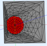
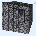
Anyhow, the horn simulated is a 60x60 horn (300 mm main flare width), beginning with a gradual transition from round to square based on the Peavey QTWG whitepaper, which, after simplifying the mesh using MeshLab looks like the picture below. Keep in mind it still rather small elements, which forces a high resolution in the solver, which brings up the time it takes. It´s really more fun with ABEC on a computer with lots of memory and a fast CPU with many cores (which I don´t have).
I did find an Akabak model of the DE250 compression driver, but there are slight incompatibilities between Akabak and ABEC, and I still haven´t figured out how to use that compression driver (which seems popular), or how to model an existing one. So I used a driver that was included in the package, as it has a one inch exit, and the author of the software has proved a good match with the measurements (I don´t know which type it is though - yet). I can´t be sure if the acoustic distance from the mouth of the compression driver to the diaphragm is entirely correct, but I´m going to assume it is for now.. If anybody wants to dive in and use ABEC, please do, and see if you can model a few good compression drivers...
The CD itself is modelled in LEM, and it connected to the BEM model via a Diaphragm element. Here you see the QTWG and the CD Diapgragm element

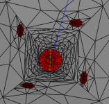
It´s the same story with the midrange drivers, except here the coupling chambers and frustum is modelled in LEM, while a Diapgragm element connects the frustom mouth to the BEM horn. ABEC has a nice feature which allows you to model a quarter of whatever you´re modelling, and really save on computation time using mirroring. However, in this case, it won´t work, unless you place the ports somewhere along a mirror axis. I didn´t spend much time seeing if I could rotate things around to fulfil that criteria, so I´m running the model with four individual midrange drivers, and no symmetry.

The frustum mouth is 15mm, throat (towards chamber outside horn) is 35mm, and wall thickness assumed to be 16mm. The mid chamber is 9cm x 1cm. (didn´t spend time trying to tweak this yet). The driver is a Visaton M10, as it has been mentioned many times in this thread, connected series-parallel. The entries center point are 1cm from the end of the QTWG.
Here´s the full "Subdomain 1", the internals of the horn, including flares:

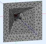
As you can see from the next picture, planes only have one "normal". So seen from the back, it looks transparent.

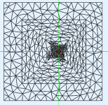
So we need to do two things: Add walls on the outside of the horn (pointing into Subdomain 2, the exterior in this case), and add an interface between Subdomain 1 (inside the horn) and Subdomain 2. The finished model looks like this (I probably should have color coded the elements now that I think about it..)

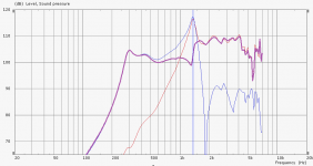
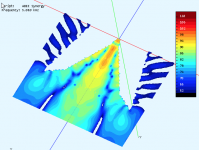
So, here are the "raw" results. No filtering applied. Higher frequencies are possible, but it eats all my memory. I could probably do something clever and split subdomains better or something to make the simulation solve faster.

Ok, so DrvGroups:
1000 = Compression driver
1001-1004 = Midrange drivers
1000-1004 = Sum of all drivers
And there is another one, which is the same as 1000-1004.
Obviously it´s going to look rubbish without any filters on. For that reason, I won´t put any polars etc here now.
I am a bit puzzled about these results. It seems like the midrange output gets boosted around 1500hz, and that the CD output is almost identical around that range. However, the sum changes things - not exactly summing flat (due to the different output levels), but still the effects seem to cancel out (green curve). Could it be that the midrange drivers reflection off the CD is represented by the midrange DrvGroup and vice-versa, inflating the numbers here?
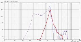
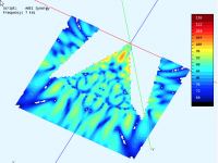
I´ll show what happens if I connect the CD to ground on both terminals (need a small resistor in between to stop the software complaining about shorts). This should remove the active output of the CD:

I highlighted the output from the diaphragm representing the compression driver. That driver is now not receiving and signal, but the model still shows 110db output! I suppose it can´t be anything else than the reflection from the midranges, coming back, out of phase, but represented on a different curve than I expected.
Any other ideas?
Other than this confusion, which I hope you guys can help me with, it seems ABEC3 is a wonderful piece of software. There is one feature missing though, which would be nice for us using DSP crossovers, and that´s to combine coupling between drivers with separate active filters to each driver group. Currently, if you want biquad filters for example, you need to do it at System level. Once you split a sim into two Systems, the interaction between them stays in the BEM model, it doesn´t travel into the LEM model. So showing one driver responding (as a passive radiator for example) from the output of another, forces you to keep them in the same System, which leaves you with passive crossovers. I have mentioned this to the author, and he has it on his "wishlist".
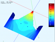
It would be really bad to now show some nice pictures of beamwidth and internal modes though. I also got to use all 10 attachments of the post.


Mod: Feel free to move this if I´m way off topic here. But I thought this thread was the big "Synergy horn everything thread".
I had a go at modelling a Synergy horn using ABEC3, a combined BEM and LEM modeller. Hoping to get some help, and possibly fuel some interest in the software, as it seems very powerful.
It had been a while since i played with a Synergy horn in Akabak, so I´m afraid i can´t give credit to those who deserve it -- I did copy scripts and spreadsheets where I found them to understand the Akabak model.
Anyhow, the horn simulated is a 60x60 horn (300 mm main flare width), beginning with a gradual transition from round to square based on the Peavey QTWG whitepaper, which, after simplifying the mesh using MeshLab looks like the picture below. Keep in mind it still rather small elements, which forces a high resolution in the solver, which brings up the time it takes. It´s really more fun with ABEC on a computer with lots of memory and a fast CPU with many cores (which I don´t have).
I did find an Akabak model of the DE250 compression driver, but there are slight incompatibilities between Akabak and ABEC, and I still haven´t figured out how to use that compression driver (which seems popular), or how to model an existing one. So I used a driver that was included in the package, as it has a one inch exit, and the author of the software has proved a good match with the measurements (I don´t know which type it is though - yet). I can´t be sure if the acoustic distance from the mouth of the compression driver to the diaphragm is entirely correct, but I´m going to assume it is for now.. If anybody wants to dive in and use ABEC, please do, and see if you can model a few good compression drivers...
The CD itself is modelled in LEM, and it connected to the BEM model via a Diaphragm element. Here you see the QTWG and the CD Diapgragm element
It´s the same story with the midrange drivers, except here the coupling chambers and frustum is modelled in LEM, while a Diapgragm element connects the frustom mouth to the BEM horn. ABEC has a nice feature which allows you to model a quarter of whatever you´re modelling, and really save on computation time using mirroring. However, in this case, it won´t work, unless you place the ports somewhere along a mirror axis. I didn´t spend much time seeing if I could rotate things around to fulfil that criteria, so I´m running the model with four individual midrange drivers, and no symmetry.
The frustum mouth is 15mm, throat (towards chamber outside horn) is 35mm, and wall thickness assumed to be 16mm. The mid chamber is 9cm x 1cm. (didn´t spend time trying to tweak this yet). The driver is a Visaton M10, as it has been mentioned many times in this thread, connected series-parallel. The entries center point are 1cm from the end of the QTWG.
Here´s the full "Subdomain 1", the internals of the horn, including flares:
As you can see from the next picture, planes only have one "normal". So seen from the back, it looks transparent.
So we need to do two things: Add walls on the outside of the horn (pointing into Subdomain 2, the exterior in this case), and add an interface between Subdomain 1 (inside the horn) and Subdomain 2. The finished model looks like this (I probably should have color coded the elements now that I think about it..)
So, here are the "raw" results. No filtering applied. Higher frequencies are possible, but it eats all my memory. I could probably do something clever and split subdomains better or something to make the simulation solve faster.
Ok, so DrvGroups:
1000 = Compression driver
1001-1004 = Midrange drivers
1000-1004 = Sum of all drivers
And there is another one, which is the same as 1000-1004.
Obviously it´s going to look rubbish without any filters on. For that reason, I won´t put any polars etc here now.
I am a bit puzzled about these results. It seems like the midrange output gets boosted around 1500hz, and that the CD output is almost identical around that range. However, the sum changes things - not exactly summing flat (due to the different output levels), but still the effects seem to cancel out (green curve). Could it be that the midrange drivers reflection off the CD is represented by the midrange DrvGroup and vice-versa, inflating the numbers here?
I´ll show what happens if I connect the CD to ground on both terminals (need a small resistor in between to stop the software complaining about shorts). This should remove the active output of the CD:
I highlighted the output from the diaphragm representing the compression driver. That driver is now not receiving and signal, but the model still shows 110db output! I suppose it can´t be anything else than the reflection from the midranges, coming back, out of phase, but represented on a different curve than I expected.
Any other ideas?
Other than this confusion, which I hope you guys can help me with, it seems ABEC3 is a wonderful piece of software. There is one feature missing though, which would be nice for us using DSP crossovers, and that´s to combine coupling between drivers with separate active filters to each driver group. Currently, if you want biquad filters for example, you need to do it at System level. Once you split a sim into two Systems, the interaction between them stays in the BEM model, it doesn´t travel into the LEM model. So showing one driver responding (as a passive radiator for example) from the output of another, forces you to keep them in the same System, which leaves you with passive crossovers. I have mentioned this to the author, and he has it on his "wishlist".
It would be really bad to now show some nice pictures of beamwidth and internal modes though. I also got to use all 10 attachments of the post.
Attachments
-
 2014-12-15 00_05_16-ABEC3 - ABEC Synergy.png77.8 KB · Views: 1,320
 -
 2014-12-15 00_07_25-ABEC3 - ABEC Synergy.png59.9 KB · Views: 1,291
 -
 2014-12-15 00_15_58-ABEC3 - ABEC Synergy.png80 KB · Views: 1,298
 -
 2014-12-15 00_19_38-ABEC3 - ABEC Synergy.png82.4 KB · Views: 1,299
 -
 2014-12-15 00_21_47-ABEC3 - ABEC Synergy.png133 KB · Views: 1,313
 -
 Screen Shot 2014-12-15 at 00.32.43.png23.2 KB · Views: 1,270
 -
 Screen Shot 2014-12-15 at 00.47.16.png22.4 KB · Views: 1,261
 -
 Screen Shot 2014-12-15 at 01.03.46.png39.6 KB · Views: 1,249
 -
 Screen Shot 2014-12-15 at 01.04.12.png58.4 KB · Views: 1,274
 -
 Screen Shot 2014-12-15 at 01.05.09.png80.8 KB · Views: 1,265
RE'
"I am a bit puzzled about these results. It seems like the midrange output gets boosted around 1500hz, and that the CD output is almost identical around that range. "
I've seen the same thing in HornResp sims of mids in a synergy. It appears to be an effect of the bandpass chamber. If you've got your port length and area in the right range then you will get that peaking right before the output plunges down to the null due to reflection off the CD diaphragm. The shape of that peak will change with port length and area...
WOW.....a lot over my head but great to see someone posted a ABEC3 simulation. Been wanting to try and use that software but havent tried yet. PLUS never saw anyone ever post it before.
Please try it! It would be great if more people used it, so I can get advice.
But just let me know if you have any questions, I´ll try to help as much as I can.I will take a stab at it today with a TH18. I have never done a SH design before in HR and dont know how anyways. Akabak was the preferred for SH simulation but I cant use that program on 64bit Win7. Unless using virtual software.
So I am glad to try this program although it might take me a long time to figure things out.
Why were the midrange exits/mouths not placed closer to the horn sides? Is it harder to do or figure out in the ABEC3 software?
So I am glad to try this program although it might take me a long time to figure things out.
Why were the midrange exits/mouths not placed closer to the horn sides? Is it harder to do or figure out in the ABEC3 software?
Ref the ABEC3 sim: http://www.diyaudio.com/forums/multi-way/88237-suitable-midrange-cone-bandpass-mid-unity-horn-187.html#post4152484
I tried to make a crossover for it. ABEC3, as I mentioned, is not easy when it comes to active crossovers when you have a system with coupled elements. It works very nicely if you have BEM elements you can treat as independent, such as a normal speaker, where you can assume minimal influence from the midrange to the tweeter, or the other way around. But in this case, I need to see the soundwaves travelling past the horn mouth into the compression driver model, reflect there, and come back out through the horn, to give the cancellation. ABEC can only apply active EQ at a system level.
So I exported the on-axis response from VACS (excellent visualisation tool from Jörg Panzer), and imported the data into Active Crossover Designer from Charlie Laub.
The crossover that seemed to work with the compression driver used. Again - this is an example driver, that has been calibrated with measurements, but I am still not sure which type it is. However, unless it has a very different acoustical properties compared to a DE250, I´m sure it can be used as proof-of-concept.
Crossover applied for mids:
Second order lowpass @ 1100, Q 1.1.
Second order lowpass @ 1100, Q0.707
Crossover applied for CD:
Second order highpass @ 1300, Q0.707
First order highpass @ 1300, Q0.707
3db gain reduction
0.05ms delay
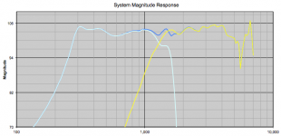
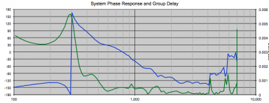
This gives the following simulated response (from 100 to 7000hz, which is what I simmed - it covers the crossover area at least).
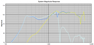
Here are the results before crossovers applied (slightly different form the previous post due to some adjustments):


So, what do you guys think - can this design work as simmed? Am I on the right track?
I tried to make a crossover for it. ABEC3, as I mentioned, is not easy when it comes to active crossovers when you have a system with coupled elements. It works very nicely if you have BEM elements you can treat as independent, such as a normal speaker, where you can assume minimal influence from the midrange to the tweeter, or the other way around. But in this case, I need to see the soundwaves travelling past the horn mouth into the compression driver model, reflect there, and come back out through the horn, to give the cancellation. ABEC can only apply active EQ at a system level.
So I exported the on-axis response from VACS (excellent visualisation tool from Jörg Panzer), and imported the data into Active Crossover Designer from Charlie Laub.
The crossover that seemed to work with the compression driver used. Again - this is an example driver, that has been calibrated with measurements, but I am still not sure which type it is. However, unless it has a very different acoustical properties compared to a DE250, I´m sure it can be used as proof-of-concept.
Crossover applied for mids:
Second order lowpass @ 1100, Q 1.1.
Second order lowpass @ 1100, Q0.707
Crossover applied for CD:
Second order highpass @ 1300, Q0.707
First order highpass @ 1300, Q0.707
3db gain reduction
0.05ms delay
This gives the following simulated response (from 100 to 7000hz, which is what I simmed - it covers the crossover area at least).
Here are the results before crossovers applied (slightly different form the previous post due to some adjustments):
So, what do you guys think - can this design work as simmed? Am I on the right track?
Attachments
Mod: Feel free to move this if I´m way off topic here. But I thought this thread was the big "Synergy horn everything thread".
I had a go at modelling a Synergy horn using ABEC3, a combined BEM and LEM modeller. Hoping to get some help, and possibly fuel some interest in the software, as it seems very powerful.
It had been a while since i played with a Synergy horn in Akabak, so I´m afraid i can´t give credit to those who deserve it -- I did copy scripts and spreadsheets where I found them to understand the Akabak model.
Anyhow, the horn simulated is a 60x60 horn (300 mm main flare width), beginning with a gradual transition from round to square based on the Peavey QTWG whitepaper, which, after simplifying the mesh using MeshLab looks like the picture below. Keep in mind it still rather small elements, which forces a high resolution in the solver, which brings up the time it takes. It´s really more fun with ABEC on a computer with lots of memory and a fast CPU with many cores (which I don´t have).
I did find an Akabak model of the DE250 compression driver, but there are slight incompatibilities between Akabak and ABEC, and I still haven´t figured out how to use that compression driver (which seems popular), or how to model an existing one. So I used a driver that was included in the package, as it has a one inch exit, and the author of the software has proved a good match with the measurements (I don´t know which type it is though - yet). I can´t be sure if the acoustic distance from the mouth of the compression driver to the diaphragm is entirely correct, but I´m going to assume it is for now.. If anybody wants to dive in and use ABEC, please do, and see if you can model a few good compression drivers...
The CD itself is modelled in LEM, and it connected to the BEM model via a Diaphragm element. Here you see the QTWG and the CD Diapgragm element
It´s the same story with the midrange drivers, except here the coupling chambers and frustum is modelled in LEM, while a Diapgragm element connects the frustom mouth to the BEM horn. ABEC has a nice feature which allows you to model a quarter of whatever you´re modelling, and really save on computation time using mirroring. However, in this case, it won´t work, unless you place the ports somewhere along a mirror axis. I didn´t spend much time seeing if I could rotate things around to fulfil that criteria, so I´m running the model with four individual midrange drivers, and no symmetry.
The frustum mouth is 15mm, throat (towards chamber outside horn) is 35mm, and wall thickness assumed to be 16mm. The mid chamber is 9cm x 1cm. (didn´t spend time trying to tweak this yet). The driver is a Visaton M10, as it has been mentioned many times in this thread, connected series-parallel. The entries center point are 1cm from the end of the QTWG.
Here´s the full "Subdomain 1", the internals of the horn, including flares:
As you can see from the next picture, planes only have one "normal". So seen from the back, it looks transparent.
So we need to do two things: Add walls on the outside of the horn (pointing into Subdomain 2, the exterior in this case), and add an interface between Subdomain 1 (inside the horn) and Subdomain 2. The finished model looks like this (I probably should have color coded the elements now that I think about it..)
So, here are the "raw" results. No filtering applied. Higher frequencies are possible, but it eats all my memory. I could probably do something clever and split subdomains better or something to make the simulation solve faster.
Ok, so DrvGroups:
1000 = Compression driver
1001-1004 = Midrange drivers
1000-1004 = Sum of all drivers
And there is another one, which is the same as 1000-1004.
Obviously it´s going to look rubbish without any filters on. For that reason, I won´t put any polars etc here now.
I am a bit puzzled about these results. It seems like the midrange output gets boosted around 1500hz, and that the CD output is almost identical around that range. However, the sum changes things - not exactly summing flat (due to the different output levels), but still the effects seem to cancel out (green curve). Could it be that the midrange drivers reflection off the CD is represented by the midrange DrvGroup and vice-versa, inflating the numbers here?
I´ll show what happens if I connect the CD to ground on both terminals (need a small resistor in between to stop the software complaining about shorts). This should remove the active output of the CD:
I highlighted the output from the diaphragm representing the compression driver. That driver is now not receiving and signal, but the model still shows 110db output! I suppose it can´t be anything else than the reflection from the midranges, coming back, out of phase, but represented on a different curve than I expected.
Any other ideas?
Other than this confusion, which I hope you guys can help me with, it seems ABEC3 is a wonderful piece of software. There is one feature missing though, which would be nice for us using DSP crossovers, and that´s to combine coupling between drivers with separate active filters to each driver group. Currently, if you want biquad filters for example, you need to do it at System level. Once you split a sim into two Systems, the interaction between them stays in the BEM model, it doesn´t travel into the LEM model. So showing one driver responding (as a passive radiator for example) from the output of another, forces you to keep them in the same System, which leaves you with passive crossovers. I have mentioned this to the author, and he has it on his "wishlist".
It would be really bad to now show some nice pictures of beamwidth and internal modes though. I also got to use all 10 attachments of the post.
Cookiemonster,
+1 on the WOW!!!
You have really outdone yourself and all us mere mortals in the comprehensive sim department. I look forward to the day when I can learn how to grid a synergy like you did. Was that pretty simple once you have a 3d model?
One thing I would like to point out is that the SPL response curves look surprisingly similar to what you can get when you model this as a pure LEM (Akabak only) model. The ability to slice and dice the pressure contours is of course only possible with 3d.
Regarding the 110dB peak at 1.5kHz - it is probably the result of the mid driver Bandpass chamber peak that is coupling into the CD diaphragm and re-radiating back out. Imagine a 1.5kHz passive radiator but it all makes sense. The horn works both ways: it provides a smooth inpedance match for sound to go from the throat out to the mouth. It also provides a great impedance match and "funnel" to take the sound from the mouth to the throat. Like putting your ear at the throat of a horn. Try that and you will notice about a 10dB gain in the volume. You will have "elephant ears". The sound from the mid driver is indeed going back into the CD and reradiating out despite the resistor you put there. In Akabak we can simply put a "OFF" switch before an element we want to leave out of the sim. Cannot ABEC3 do that?
Related to that - I have personally experienced something similar in real life. I have a tractrix horn with a full range driver as the tweeter. When I was testing the mid driver with band pass port injection, I noticed sounds (mechanical movement) of the tweeter cone. It was resonant at the peak band pass frequency. I shorted the leads to the tweeter and the mechanical noise went away as well as a large reduction in sympathetic cone motion on the tweeter acting as a passive radiator. The overall all SPL went up because the tweeter was no longer flapping around usin it's suspension as a sound damper. The harnonic distortion went down too. So this tells me that the CD should be connected to an amp with a high damping factor and low output impedance so that it can resist being excited by the mid cone drivers.
So this tells me that the CD should be connected to an amp with a high damping factor and low output impedance so that it can resist being excited by the mid cone drivers.
Or, as Danley does, with a small inductor across the CD, as a last part of the crossover, to also in effect stiffen the suspension at lower frequencies.
Or, as Danley does, with a small inductor across the CD, as a last part of the crossover, to also in effect stiffen the suspension at lower frequencies.
Good idea and probably fine for a CD that is high passed at 1kHz but my full range driver goes down to 400Hz. That would be one big coil.
8" closed back mid: http://www.sica.it/media/Z004930.pdf
paper surround
paper surround
8" closed back mid: http://www.sica.it/media/Z004930.pdf
paper surround
Hi All
I did read that having a closed back will act as a low pass, I do not now if a closed mid do this but I presume yes.
I have simulated a horn without a back chamber and it looks to go much higher
regards
hi folks,
Just a quick question, I have been mucking around with some models in sketchup looking at a 3 way SH + tapped horn sub for Home music use. When we look at placing mids I understand that we need to take flare rate and the 1/4 wavelength of the crossover into consideration so that the port holes are not 'seen' by the CD. With a CD to mids XO of 1000hz (1/4 wavelength of 85mm) do I measure that on the face of the horn panel, or as if it is projecting through the center of the horn out of the CD?
Thanks,
Mark
I mostly see SH-60 DIY Builds. I am wanting to build a 3 way model and wonder why the SH-60 over other designs like SH-69. Is this due to the coverage being to wide in room (90x60 over the 60x60) or just that it is easier to build the 60x60 horns?
Sorry for what might seem like a silly question.
Steve
Sorry for what might seem like a silly question.
Steve
Has someone did see this one inside? a coaxial driver and two 8 inches, looks interesting to test in future.
SM60F | Danley Sounds Labs | Danley Sound Labs, Inc.
regards
SM60F | Danley Sounds Labs | Danley Sound Labs, Inc.
regards
Yes.looks interesting
Coax with detachable comp. driver's horn seems to be the most convenient to use in synergy..
- Home
- Loudspeakers
- Multi-Way
- Suitable midrange cone, for bandpass mid in Unity horn.