Now you've just completely lost me
Maybe I didn't asked the right question - I'll try to rephrase.
With a 6.5" driver you have diameter of appx. 130mm. Let's say you have to place the holes near the egde of the cone and not far apart. This means that soundwaves emitted farthes away from the ports will travel appx. 98mm. before it hits a port With a 1500Hz x-over a 1/4 wavelength is 57.3mm. Will this not cause delay/phase problems?
/Thomas
The sound does not originate from a specific point on the cone of the driver. The entire volume under the cone gets pressurized and enters into the horn through the port. There are no delay issues related to placement of the ports in relation to the cone. At least I have never been able to measure any.
Now you've just completely lost me
Maybe I didn't asked the right question - I'll try to rephrase.
With a 6.5" driver you have diameter of appx. 130mm. Let's say you have to place the holes near the egde of the cone and not far apart. This means that soundwaves emitted farthes away from the ports will travel appx. 98mm. before it hits a port With a 1500Hz x-over a 1/4 wavelength is 57.3mm. Will this not cause delay/phase problems?
/Thomas
Over on AudioAsylum, years ago, Danley mentioned that he did some experiments with DSP delay to tighten up the integration with the various drivers. He said that it made a subtle but audible difference. I'm too lazy to dig up the posts, but it struck me that this would be one way to make some small improvements to an already good design. I have two miniDSP that are begging to get used here
")
Also, the VTC Paraline boxes use DSP, and they've published the raw and processed data. (A Paraline and a Synergy horn have lots in common.)
Nice!
Do you have more deatails about what gave this nice simulation.
Like for example.
How many speakers?
Portsize?
Dimensions of the horn?
Frontchamber volume?
Area of the horn that it taps in to?
Flare rate?
You understand that I want to be spoonfeed with all the datails here..
Do you have more deatails about what gave this nice simulation.
Like for example.
How many speakers?
Portsize?
Dimensions of the horn?
Frontchamber volume?
Area of the horn that it taps in to?
Flare rate?
You understand that I want to be spoonfeed with all the datails here..
Nice!
Do you have more deatails about what gave this nice simulation.
..
No problem. The Akabak script I hacked together would be confusing to most people, so I need to clean it up before posting it. I’ll try to do that later today.
No problem. The Akabak script I hacked together would be confusing to most people, so I need to clean it up before posting it. I’ll try to do that later today.
Thank you John!
That's a hell of alot better then what I can come up with using my newbie Akabak skills.
Looking forward to seeing your script!
/Thomas
Last edited:
If anyone hasn't check out Scott's Tumblr, there are some very exciting pics of some Synergy horns coming together! (And also what appears to be a Paraline horn?) Looks like he's using the little Dayton 3" drivers:
While their parameters don't fit the criteria posted on the first page of this thread, I'd long wondered if they'd work. The phase plug might extend the high frequency response usefully, and also lowers the MMS and raises the FS.
An externally hosted image should be here but it was not working when we last tested it.
While their parameters don't fit the criteria posted on the first page of this thread, I'd long wondered if they'd work. The phase plug might extend the high frequency response usefully, and also lowers the MMS and raises the FS.
Thanks for the link. I am still trying to learn more before I try and experiment. I was going to try and buy a few of the celestion 5" mids but just have not committed yet. Also looked at maybe doing a dual PHL 8" SH but really like the idea of doing a SH64.
That being said I am just sitting back and trying to learn as you guys keep experimenting. Then hopefully I be wasting too much material.
Look forward to seeing how these 3" mids work.
That being said I am just sitting back and trying to learn as you guys keep experimenting. Then hopefully I be wasting too much material.
Look forward to seeing how these 3" mids work.
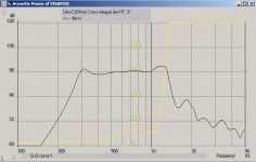
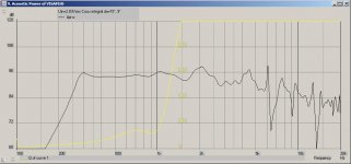
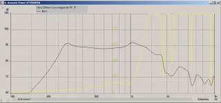
Sorry this took so long. Been busy with the kid's school projects and sports. I had to make some changes to the first script because it was physically impossible to build; things would not fit in the real world. The first attachment is the raw simulated midrange response. The second attachment is the simulated response with the compression driver added in without a crossover. I do this to see how close the drivers are to naturally summing together. If this normally looks good, then the crossover work is a lot easier. See the script below. Ignore the resistors, caps, and inductors in the top of the script. They are not being used. Also note that I have the amplifier output impedance set to 2 ohms for a tube amp.
System 'Unity'
Def_Driver 'CompDriver' | D220Ti-OMF compression driver
Sd=15.2cm2
Bl=8.0Tm
Cms=3.45E-05m/N
Rms=0.4Ns/m
Fs=850Hz
Le=0.12mH
Re=12.5ohm
ExpoLe=0.618
Def_Driver 'MidDriver' |Visaton M 10 4" mid
Sd=59.86cm2
Bl=3.18Tm
Cms=3.23E-05m/N
Rms=1.07Ns/m
fs=609Hz
Le=0.33mH
Re=7.1ohm
ExpoLe=0.618
Def_Const | Unit is cm
{
FcMid_Len=1.9e-2; | Front Mid chamber length
FcMid_dD=8.5086e-2; | Front Mid chamber diameter
FcPortMid_Len=2.54e-2; | Mid Enrty Port length
FcPortMid_dD=2.2e-2; | Mid Entry Port diameter
Rg=2.0; |Amplifier output impedance (ohms)
R1Comp = 39; |Compression driver Crossover R1 resistance (ohms)
R2Comp = 25; |Compression driver Crossover R2 resistance (ohms)
R3Comp = 8.2; |Compression driver Crossover R3 resistance (ohms)
C1Comp = 5.6e-6; |Compression driver Crossover C1 capacitor (Farads)
C2Comp = 1.0e-6; |Compression driver Crossover C2 capacitor (Farads)
C3Comp = .33e-6; |Compression driver Crossover C1 capacitor (Farads)
C4Comp = 22e-6; |Compression driver Crossover C2 capacitor (Farads)
L1Comp = 1.8e-3; |Compression driver Crossover L1 inductor (Henries)
L2Comp = 0.033e-3; |Compression driver Crossover L1 inductor (Henries)
C1Mid = 45e-6; |Mid Driver Crossover C1 capacitor (Farads)
R1Mid = 20; |Mid Driver Crossover R1 resistance (ohms)
R2Mid = 5.6; |Mid Driver Crossover R2 resistance (ohms)
L1Mid = 3.3e-3; |Mid Driver Crossover L1 inductor (Henries)
S1 = 1.275e-4; |WG1 throat area & Comp phase plug(sq cm)
S2 = 5.067e-4; |WG2 mouth area & horn segment 2 throat area & compression driver exit(sq cm)
S3 = 14.19e-4; |WG3 mouth area & horn segment 3 throat area(sq cm)
S4 = 36.21e-4; |WG4 mouth area & horn segment 4 throat area & midrange tap point(sq cm)
S5 = 975e-4; |mouth
S6 = 1425e-4; |mouth flare out
L12 = 4.2e-2; |WG1 axial length(cm)
L23 = 1.7e-2; |WG2 axial length(cm)
L34 = 1.3e-2; |WG3 axial length(cm)
L45 = 24.3e-2; |mouth flare
L56 = 1.5e-2; |mt
VrcComp = 0.08e-3; |compression driver Rear chamber volume (litres)
LrcComp = 0.84e-2; |compression driver Rear chamber average length (cm)
VtcComp = 0.75e-6; |compression driver Throat chamber volume (cc)
AtcComp = 15.520e-4; |compression driver Throat chamber cross-sectional area (sq cm)
ArcComp = VrcComp / LrcComp; |Conversions for CompDriver
LtcComp = VtcComp / AtcComp;
Sd=59.86E-02;
}
Duct 'CompRearChamber' Node=30=31
SD={ArcComp} Len={LrcComp} Visc=0
Driver 'D1' Def='CompDriver' Node=0=2=31=32
Duct 'CompFrontChamber' Node=32=140
SD={AtcComp} Len={LtcComp} Visc=0
Radiator 'Diaphragm2' Node=100 SD={Sd} Label=2
Radiator 'Diaphragm3' Node=101 SD={Sd} Label=3
Radiator 'Diaphragm4' Node=102 SD={Sd} Label=4
Radiator 'Diaphragm5' Node=103 SD={Sd} Label=5
Driver 'D2' Def='MidDriver' Node=2=40=100=120
Driver 'D3' Def='MidDriver' Node=40=0=101=121
Driver 'D4' Def='MidDriver' Node=2=41=102=122
Driver 'D5' Def='MidDriver' Node=41=0=103=123
Duct 'DuMid_Fc1' Node=120=130 dD={FcMid_dD} Len={FcMid_Len}
Duct 'DuMid_Fc2' Node=121=131 dD={FcMid_dD} Len={FcMid_Len}
Duct 'DuMid_Fc3' Node=122=132 dD={FcMid_dD} Len={FcMid_Len}
Duct 'DuMid_Fc4' Node=123=133 dD={FcMid_dD} Len={FcMid_Len}
Duct 'DuMid_BP1a' Node=130=170 dD={FcPortMid_dD} Len={FcPortMid_Len}
Duct 'DuMid_BP2a' Node=130=170 dD={FcPortMid_dD} Len={FcPortMid_Len}
Duct 'DuMid_BP1b' Node=131=170 dD={FcPortMid_dD} Len={FcPortMid_Len}
Duct 'DuMid_BP2b' Node=131=170 dD={FcPortMid_dD} Len={FcPortMid_Len}
Duct 'DuMid_BP1c' Node=132=170 dD={FcPortMid_dD} Len={FcPortMid_Len}
Duct 'DuMid_BP2c' Node=132=170 dD={FcPortMid_dD} Len={FcPortMid_Len}
Duct 'DuMid_BP1d' Node=133=170 dD={FcPortMid_dD} Len={FcPortMid_Len}
Duct 'DuMid_BP2d' Node=133=170 dD={FcPortMid_dD} Len={FcPortMid_Len}
Resistor 'Amplifier Rg' |Amplifier output impedance
Node=1=2
R={Rg}
Waveguide 'WG1'
Node=140=150
STh={S1}
SMo={S2}
Len={L12}
T=1
Waveguide 'WG2'
Node=150=160
STh={S2}
SMo={S3}
Len={L23}
T=1
Waveguide 'WG3'
Node=160=170
STh={S3}
SMo={S4}
Len={L34}
Conical
Waveguide 'WG4'
Node=170=180
STh={S4}
SMo={S5}
Len={L45}
Conical
Waveguide 'WG5'
Node=180=190
STh={S5}
SMo={S6}
Len={L56}
Conical
Radiator 'Horn mouth'
Node=190
SD={S6}
x=0
y=0
z=0
HAngle=0
VAngle=0
Attachments
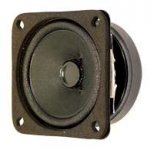
Visaton FRS8M ? (better power handling)
FRS 8 M - 8 Ohm
ahh, and one with the desired closed back (I guess)
http://www.visaton.de/de/chassis_zubehoer/konus_mt/mr130_8.html
and smaller
http://www.visaton.de/de/chassis_zubehoer/breitband/frs7w_8.html
FRS 8 M - 8 Ohm
ahh, and one with the desired closed back (I guess)
http://www.visaton.de/de/chassis_zubehoer/konus_mt/mr130_8.html
and smaller
http://www.visaton.de/de/chassis_zubehoer/breitband/frs7w_8.html
Visaton FRS8M ? (better power handling)
FRS 8 M - 8 Ohm
ahh, and one with the desired closed back (I guess)
MR 130 - 8 Ohm
and smaller
FRS 7 W - 8 Ohm
The problem with those mids is the foam roll surround.
The problem with those mids is the foam roll surround.
ah, ok
anyway, the M10 also appear to have good power handling when crossed high(800hz)
I case you haven't noticed ...
M10 is also available as R models without the closed back
would be nice if it would do 2khz
(if I remember correctly, the M10 was considered very good because of its flat shallow cone)
How would you input a driver like this in hornresp? It would be fun to se if one can aproximate your simulations in it instead.
And to the big question. JLH when will you learn abec 3?
http://hal.archives-ouvertes.fr/docs/00/81/12/56/PDF/hal-00811256.pdf
ABEC-Studies
It looks good..
And to the big question. JLH when will you learn abec 3?
http://hal.archives-ouvertes.fr/docs/00/81/12/56/PDF/hal-00811256.pdf
ABEC-Studies
It looks good..
Thank you for sharing your M10 script, John - it looks great!
Them damn kids taking up all your audio time. Mine are like that too
I'm still working with the little Ciare HT080 - or trying to! But since I can't measure the T/S parameters do to it's resistive (almost flat) impendance, I've decided to just build a pair of scrap horns and do it the old-fashioned way - by trial and error!
/Thomas
JLH when will you learn abec 3?
Probably never. Horn Response and Akabak do everything I need. Akabak was bad enough to learn. I have plenty enough other things that consume my time without the need to learn more software.
- Snip...
S1 = 1.275e-4; |WG1 throat area & Comp phase plug(sq cm)
S2 = 5.067e-4; |WG2 mouth area & horn segment 2 throat area & compression driver exit(sq cm)
S3 = 14.19e-4; |WG3 mouth area & horn segment 3 throat area(sq cm)
S4 = 36.21e-4; |WG4 mouth area & horn segment 4 throat area & midrange tap point(sq cm)
S5 = 975e-4; |mouth
S6 = 1425e-4; |mouth flare out
L12 = 4.2e-2; |WG1 axial length(cm)
L23 = 1.7e-2; |WG2 axial length(cm)
L34 = 1.3e-2; |WG3 axial length(cm)
L45 = 24.3e-2; |mouth flare
L56 = 1.5e-2; |mt
Waveguide 'WG1'
Node=140=150
STh={S1}
SMo={S2}
Len={L12}
T=1
Waveguide 'WG2'
Node=150=160
STh={S2}
SMo={S3}
Len={L23}
T=1
Waveguide 'WG3'
Node=160=170
STh={S3}
SMo={S4}
Len={L34}
Conical
Waveguide 'WG4'
Node=170=180
STh={S4}
SMo={S5}
Len={L45}
Conical
Waveguide 'WG5'
Node=180=190
STh={S5}
SMo={S6}
Len={L56}
Conical
Radiator 'Horn mouth'
Node=190
SD={S6}
x=0
y=0
z=0
HAngle=0
VAngle=0
...Snap!
John, would you please explain the function of the additional waveguide (W3) just before the mid tap-point. Why not just make one waveguide from the compession driver throat (W2) to the mid tap-point (W4)?
Does my question make sence to you or am I talking rubbish?
/Thomas
WG1 is the beginning of compression driver's phase plug.
WG2 is the compression driver exit and beginning of the horn.
WG3 is the beginning of the round to square transition section at the throat of the horn.
The beginning of WG4 is where the mids tap in.
WG1 and WG2 are exponential and the rest are conical.
WG2 is the compression driver exit and beginning of the horn.
WG3 is the beginning of the round to square transition section at the throat of the horn.
The beginning of WG4 is where the mids tap in.
WG1 and WG2 are exponential and the rest are conical.
WG1 is the beginning of compression driver's phase plug.
WG2 is the compression driver exit and beginning of the horn.
WG3 is the beginning of the round to square transition section at the throat of the horn.
The beginning of WG4 is where the mids tap in.
WG1 and WG2 are exponential and the rest are conical.
Thank you, John - I see it now!
/Thomas
The problem with those mids is the foam roll surround.
worth to note that what may appear like foam surround could well be coated cloth
several small Visaton are
if not specificly saying foam or rubber on Visaton site, I take it they are coated cloth surround
weird sitting here looking for smooth response curves on cheap 10EUR drivers

Attachments
- Home
- Loudspeakers
- Multi-Way
- Suitable midrange cone, for bandpass mid in Unity horn.