Frankly, we usuallyhow the location of these components are decided on schematic.
Yes, that's a wise option. Most circuits are very similar and we cannot "invent" too much. My doubts are mainly with circuit tuning and how to connect the tone bank. Now, Thomas has helped a lot on that matter.Frankly, we usuallycopystudy other amplifiers we like.
My circuit has, as well, potentiometers for changing the bias and gain. Due to my lack of experience, I cannot target a perfect value but, on the other hand, it gives me more sonic choices when playing going from warm to cold and high to low gain.
Cheers,
Pedro
Hi Thomas,
Thanks a lot for your detailed explanation. It was really helpful.
Thanks,
Pedro
Thanks a lot for your detailed explanation. It was really helpful.
So as the cathode follower acts as a buffer, it will drive the tone stack better. Makes sense!Well, you can change it according to taste.
The tone stack sucks a lot of signal when driven by a gain stage, as in a fender amp (right after the fist stage).
The cathode follower deals better with this kind of load and presents a lower signal attenuation.
The problem is, you cannot start with a cathode follower. Its gain is much lower, and at the initial stages you need to amplify the guitar signal to usable levels, so it comes later in the circuit.
Yes, I thought that would be the case since it would degrade the SNR. As I see some circuits making use of that, I was wondering if there was an advantage in doing that.Regarding the volume control, I don't like volume controls before the first stage. You are attenuating it before you even amplified it.
When you amplify you also amplify noise at the grid of the first stage(sensible node).
I think I will either put a switch on the circuit, which will allow me to bypass the tone stack, or just remove the tone stack from the circuit as in many circuits. I am tempted to do a version of the Super Fly, which you suggested some time ago.Subminiature tubes have another problem. If you are using direct heated tubes they probably have a very low MU, so it will take more stages to get it to distort. Due to the direct heated cathode you cannot easily implement a cathode follower, meaning you are stuck with a very lossy tony control.
Thanks,
Pedro
Hi,Pedro,
Well No I can't. (I haven't built anything Class B)
No wait i do see it. It probably fine for Class B PP.
Someone else who knows more could comment for Class A PP, as that case I doubt.
I would say you probably want to fix Class and stick to one class
I can see the intersection of 180 anode volts and quiescent current of 30mA, which is 100% dissipation for that valve.
I am using push-pull in class AB. From what I've read, you can reach maximum power and even go above it.
The valve I've got is the 6P30B-R which goes up to 6.5W, whereas the curves I've attached here are for the valve without the "-R", which goes up to 5.5W.
Regarding biasing in push-pull, please check this excellent article by Merlin (Valve Wizard):
https://valvewizard.co.uk/pp.htmlAnd by Rob Robinette:
https://robrobinette.com/Drawing_Tube_Load_Lines.htm
Cheers,
Pedro
I think they expect that you connect something with a stronger signal, as a preamp or an LP player.As I see some circuits making use of that, I was wondering if there was an advantage in doing that.
The superfly uses indirect heated cathodes. They have higher filament currents and normal Mu levels (6112 has a Mu of 100?), so you can use a tone stack.I am tempted to do a version of the Super Fly, which you suggested some time ago.
My comment was considering the 5672 with a Mu of 5 or the 5678 with a mu of 10 (or is it 20?). Anyway, with only 2 stages I would stick to a single pot tone control, with low attenuation (treble cut).
cheers,
Thomas
Hi Thomas,I think they expect that you connect something with a stronger signal, as a preamp or an LP player.
The superfly uses indirect heated cathodes. They have higher filament currents and normal Mu levels (6112 has a Mu of 100?), so you can use a tone stack.
My comment was considering the 5672 with a Mu of 5 or the 5678 with a mu of 10 (or is it 20?). Anyway, with only 2 stages I would stick to a single pot tone control, with low attenuation (treble cut).
cheers,
Thomas
The tubes I have are the 6N17B, 6N16B and 6P30B-R. On the superfly I would use one 6N17B and a 6N16B. The differences in the bias resistors should be minimal.
Many Thanks,
Pedro
Yes I agree.Hi,
I am using push-pull in class AB. From what I've read, you can reach maximum power and even go above it.
The valve I've got is the 6P30B-R which goes up to 6.5W, whereas the curves I've attached here are for the valve without the "-R", which goes up to 5.5W.
Regarding biasing in push-pull, please check this excellent article by Merlin (Valve Wizard):
https://valvewizard.co.uk/pp.htmlAnd by Rob Robinette:
https://robrobinette.com/Drawing_Tube_Load_Lines.htm
Cheers,
Pedro
7W is the absolute maximum dissipation however.
5 to 6W may be a safer option (longer lasting valves)
(In SE pentode, with Va at 300V, Ik at 16mA, I.e. just 5W, for 0.8W output)
Going higher than 5W idle (DC) dissipation per tube will cause one of the two anodes to red plate (6P30B-R)
try it and see... I know of what I speak (in this case)
Interestingly, the standard 6P30B valve is lower rated, due to single anode and narrower glass envelope.
However, used within limits, they are better quality - and actually have a getter.
6P30B-R is getterless, and I have found a few examples with excessive grid current (gassy or soft vacuum)
So...amplifier class is irrelevant, power dissipation per tube remains the same (can't change physics)
*that is to say I am not arguing with you, but DC dissipation PER tube, is still the same as Class A...
Go beyond 5W DC power per tube and the plates will start to glow (regardless of amplifier class)
Last edited:
Hi,Yes I agree.
7W is the absolute maximum dissipation however.
5 to 6W may be a safer option (longer lasting valves)
(In SE pentode, with Va at 300V, Ik at 16mA, I.e. just 5W, for 0.8W output)
Going higher than 5W idle (DC) dissipation per tube will cause one of the two anodes to red plate (6P30B-R)
try it and see... I know of what I speak (in this case)
Interestingly, the standard 6P30B valve is lower rated, due to single anode and narrower glass envelope.
However, used within limits, they are better quality - and actually have a getter.
6P30B-R is getterless, and I have found a few examples with excessive grid current (gassy or soft vacuum)
So...amplifier class is irrelevant, power dissipation per tube remains the same (can't change physics)
*that is to say I am not arguing with you, but DC dissipation PER tube, is still the same as Class A...
Go beyond 5W DC power per tube and the plates will start to glow (regardless of amplifier class)
From what I understand, the advantage is to use push-pull instead of SE (independently of the class). In my case, I am using push-pull, in class AB, since it is more efficient. But you are right, from DC point of view the consumption is the same. The valve is biased for a given voltage/current and that's it.
Anyhow, I just want about 0.5W of output power, so I believe I don't have the need to go closer to the max dissipation curve.
I didn't know that the 6P30B is better than the -R version. What I've noticed, though, is that these valves are a bit noisy compared to the triodes. Is it like this for all pentodes?
Regarding "my" design, I am considering lowering the supply from 180V to, let's say, 150V.
I've even played with the 6N16B at very low voltages (≈15V) and fed the output to a class D power amp module (I tried a class AB as well) that you get from eBay for £1.50 and it works! Volume isn't great and if I increase the volume of the guitar to the max, it will distort a lot and get a bit muddy. Lowering to 6 or 7 works fine.
Cheers,
Pedro
Yes this is my point 👉Hi,
From what I understand, the advantage is to use push-pull instead of SE (independently of the class). In my case, I am using push-pull, in class AB, since it is more efficient. But you are right, from DC point of view the consumption is the same. The valve is biased for a given voltage/current and that's it.
Anyhow, I just want about 0.5W of output power, so I believe I don't have the need to go closer to the max dissipation curve.
I didn't know that the 6P30B is better than the -R version. What I've noticed, though, is that these valves are a bit noisy compared to the triodes. Is it like this for all pentodes?
Regarding "my" design, I am considering lowering the supply from 180V to, let's say, 150V.
I've even played with the 6N16B at very low voltages (≈15V) and fed the output to a class D power amp module (I tried a class AB as well) that you get from eBay for £1.50 and it works! Volume isn't great and if I increase the volume of the guitar to the max, it will distort a lot and get a bit muddy. Lowering to 6 or 7 works fine.
Cheers,
Pedro
0.5W audio power is easily done, no need for 100% idle dissipation for 0.5W audio output.
In SE 5W DC idle for about 0.8W Audio, so you should be able to do more Audio, with less Idle power in Class B (not sure why AB is important, for a instrument amplifier, or what clipping behaviour and recovery would be like in such a case)
Though, you could do that with 6N16B and run hot.
The amp is very quiet and only with the volume at 10, I can actually ear something that is reasonable.
I guess I will have to change the 6N16B in the pre-amp for a 6N17B.
And, as Thomas said, the tone stack sucks volume.
Maybe adding a buffer (another valve or a JFET), the tone stack would be properly driven.
Any thoughts on this?
Cheers,
Pedro
I guess I will have to change the 6N16B in the pre-amp for a 6N17B.
And, as Thomas said, the tone stack sucks volume.
Maybe adding a buffer (another valve or a JFET), the tone stack would be properly driven.
Any thoughts on this?
Cheers,
Pedro
Hi,The best I could find are 100 V line transformers with a 0.625 W tap. I gave you some examples. This transforms to 16 kohms which might fit well enough. The CT is the 2.5 W tap.
Best regards!
Thanks.
And that was exactly what I've done.
Centre tap 2.5W and then Common and 0.625W to the extremes.
Cheers,
Pedro
Last edited:
Hi,Remember that a self balancing, self inverting output pair requires double the signal level compared to just one tube, and triodes in general require high drive signals.
Thanks for the reply.
Does the same apply to "normal" push-pull configuration with phase-inverter? Would this one be able to perform better, or would it be the same regarding power?
Cheers,
Pedro
Hi Pedro,
it depends on the PI. Basically, the finals' gain is as it can be expected from the operting point. The PI's gain depends on the design: With two triodes, it equals the first triode's in a Paraphase or Concertina, or it is half a triode's gain in the LTP.
With a dedicated PI output power will increase with fix biased finals, and it might increase with cathode biasing.
Best regards!
Thank you.Hi Pedro,
it depends on the PI. Basically, the finals' gain is as it can be expected from the operting point. The PI's gain depends on the design: With two triodes, it equals the first triode's in a Paraphase or Concertina, or it is half a triode's gain in the LTP.
With a dedicated PI output power will increase with fix biased finals, and it might increase with cathode biasing.
Best regards!
")
Best regards,
Pedro
Hi guys,
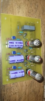
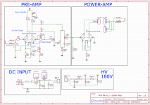
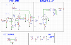
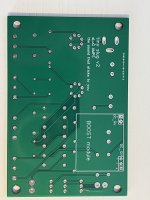
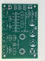
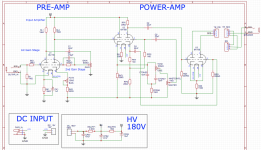
Since last update, I have made 2 versions of the amp attached to this post.
I've called the amp "tiny Slug". I have another under development called "little Slug", which schematic is attached too. This one has a phase inverter and a buffer for the tone stack.
Please feel free to criticise my designs !
To be honest I would like to open my own company to do guitar amps, but I have a reliable full-time job that pays my bills.
Cheers,
Pedro
Attachments
Last edited:
- Home
- Live Sound
- Instruments and Amps
- Subminiature tube/valve guitar amplifier