Can someone please help me finding the pinout for this tube?
hook up 6.3V to leads across from each other. When the heater glows you've found pins 4 and 8. The rest can be found from there.
Thanks both.
With a multimeter, I've measure the resistance between each wire in one triode with other wires on the second triode.
Only one combination measured about 30 ohms or so. So, I guess those two are the heaters.
All the others are high impedance.
Now, I can use Trawglodyte's idea and put there 6.3V to see if it glows.")
Cheers,
Pedro
With a multimeter, I've measure the resistance between each wire in one triode with other wires on the second triode.
Only one combination measured about 30 ohms or so. So, I guess those two are the heaters.
All the others are high impedance.
Now, I can use Trawglodyte's idea and put there 6.3V to see if it glows.
Cheers,
Pedro
Hi guys,
I've started doing my amp. Finally !!
So I can get the sound I want, I started putting everything into a breadboard.
As a first step, I've wired the first stage of the pre-amp and used a class D 3W power amp module, which I bought off eBay, to drive the speaker.
If I connect my smartphone to the class D amp, the sound is very good.
However, when I connect the valve pre-amp to it has loads of noise, as it was statics from a TV or similar sound to heavy rain.
The guitar is working and the sound is not bad at all.
When I power off the amplifier, then it sounds very well. As I have a "big" cap on the supply, I still have good 30seconds before it really turns off.
I am using 2 SMPS, one is a boost (180 V) and another is a buck, to set the heater voltage to 6.3V.
The noise is pretty loud, but when the heater turns on, it gets even louder.
So, I've decided to put a cap on the 180V power rail, which was removed from a power supply from an iMac. It is a Rubycon 180uF and 450V.
Causes for this?
- Bad/inexisting ground?
- The use of SMPS instead of linear regulators?
- Would some adequate filtering on the SMPS improve this? From the iMac power supply, I can salvage every single component.
Ideas please?
Cheers,
Pedro
Last edited:
Hi, nice to see that you went on with this build.
My first question would be, which kind of input the 3W class D amp expects? Do you have to separate grounds for each input (if it is stereo)?
Since turning it off works, it is probably one of the SMPS that introduces a lot of noise. I guess it gets louder when you power the heaters because the noise of the preamp adds up to the noise in the power amp.
Some test I would do:
- With the 180V SMPS on and heater off ground the input of the power amp. Any noise? Probably not.
- With the 180V SMPS on and heater off ground the input of the last stage in the preamp. The cable between preamp and power amp could act as an antenna and introduce some noise, but it should be way less than what the power amp expects, thus not as loud.
- With heaters on and 180V SMPS off check noise. Is it louder with the heaters on, without plate voltage or the other way around?
About filtering. You can filter the B+ and the 6.3v with some RC or RL filters, but since both SMPS are working at high frequencies they will also emanate noise. Part of the circuit acts as an antenna and will pic it up. This gives me the idea...
- Check the noise if both SMPS are on, but not connected to the preamp (without load). If there is noise, then the SMPS are emanating it. You can try wrapping them in aluminium foil and grounding the foil. First make sure that the foil won't touch the circuit by using some plastic foil. This way you can make a small cage that will contain some of the noise. It needs to be grounded, otherwise it will act like an antenna and make things worse by increasing the emanated noise.
Later, when you put your circuit in a box, if you position the SMPS closer to the walls, and the walls are made of metal, and grounded, they will shield part of the noise, reducing the electric field and the noise emission.
If you have a transformer, try powering the preamp with it. The noise should be reduced, and you can check if the circuit is working as intended (no missing ground). Later you can add the SMPSs and try to handle the noise they produce.
Using shielded wire for the inputs or sensitive nodes in the circuit also helps.
Hi Thomas,
Thanks for the detailed answer.
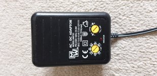
Regarding ground, I don't have a "real" ground, since I am using an old transformer to power both SMPS (please check the pictures attached).
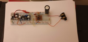
I've attached a video just for you to hear the noise and a picture of the breadboard.
Cheers,
Pedro
Thanks for the detailed answer.
Regarding ground, I don't have a "real" ground, since I am using an old transformer to power both SMPS (please check the pictures attached).
I've attached a video just for you to hear the noise and a picture of the breadboard.
Cheers,
Pedro
Attachments
Hello guys,
I am making some progress with the amplifier.
The power stage is now a pp stage.
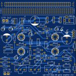
I did the PCB on EasyEda, but I have some doubts regarding grounding and track width.
Grounding:
1 - is it better to have a ground plane or star-connect all grounds?
2 - in case of using a ground plane, should I use one or separate planes for power and signal?
Track width:
What should be the with of the power tracks for a supply of 180V (I am using 3mm )?
The anode current of the 6P30B-R is around 50mA and the heater 400mA !
Any suggestions please?
Attached there is a screenshot of the PCCB on Easyeda. I've added a small area for prototyping on the top.
Cheers,
Pedro
I am making some progress with the amplifier.
The power stage is now a pp stage.
I did the PCB on EasyEda, but I have some doubts regarding grounding and track width.
Grounding:
1 - is it better to have a ground plane or star-connect all grounds?
2 - in case of using a ground plane, should I use one or separate planes for power and signal?
Track width:
What should be the with of the power tracks for a supply of 180V (I am using 3mm )?
The anode current of the 6P30B-R is around 50mA and the heater 400mA !
Any suggestions please?
Attached there is a screenshot of the PCCB on Easyeda. I've added a small area for prototyping on the top.
Cheers,
Pedro
Attachments
Current in audio circuits moves in circles. Route and ground accordingly.
Digital bits benefit from ground and power planes (yes, there are exceptions) but keep these separate from the rest of the circuit as far as possible.
50mA is find for standard tracks. 1/2A needs a little more thought (as you will get some voltage drop) and needs to be isolated from the audio bits (see the 1st sentence).
Hi guys,
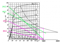
I am dimensioning the output stage and have one doubt. When drawing the class A load line, I move the load line close to the max power curve. If I go really close to the curve I will operate in class A only. Is there a way to move up the class B line as well?
I've done some experiments. Please check the pictures attached.
Cheers,
Pedro
Attachments
Line transformers can be used for push pull, not much good for single ended. But you cannot use any line transformer, look here for info on what & how.Thanks for your reply.
Well, Thomas Hafemanm says that Line transformers are good enough for low power guitar amplifiers.
He has done many different amplifiers. Please check on YouTube. They are really awesome.
Battery Powered Tube Amplifier : 4 Steps (with Pictures) - Instructables
Cheers,
Pedro
The Omnitronic mentioned by Kay pirinha is very suitable for PP. You could use an 8 ohm speaker to get 32k primary inductance. I think using a 4 ohm pc speaker is not the best way of saving money, a real guitar speaker is much more efficient and thus louder. The speaker will most often be by far the most expensive part of the project, that's the reality.
Hi guys,
I have a fundamental doubt on the tone stack integration into the amp.
Where to put the TS in the circuit vs the vol pot is not clear to me.
I understand that putting the pot on the output of the 1st stage will change the gain since, for ac, the pot's resistance will appear in parallel with the anode resistor.
But I believe that put it on the output of the second stage would achieve the same purpose. I understand, aswell, that the pots on the tone stack will also change the game in diverse frequencies. However, they wont change the volume. So, can you please explain to me how the location of these components are decided on schematic. Finally, what's the advantage of having the volume pot connected to the grid of the first valve instead?
-Thanks in advance, Pedro.
Well, you can change it according to taste.
The tone stack sucks a lot of signal when driven by a gain stage, as in a fender amp (right after the fist stage).
The cathode follower deals better with this kind of load and presents a lower signal attenuation.
The problem is, you cannot start with a cathode follower. Its gain is much lower, and at the initial stages you need to amplify the guitar signal to usable levels, so it comes later in the circuit.
As I understand it, it is also better to cut frequencies when they are already there, at the end of the line.
To me, cutting it at the beginning involves more guess work, since you never know which frequencies will result from distortion and harmonics.
On the other hand, with a tone stack after a gain stage, the signal loss will be so brutal, you might end up without a lot of distortion.
Regarding the volume control, I don't like volume controls before the first stage. You are attenuating it before you even amplified it.
When you amplify you also amplify noise at the grid of the first stage(sensible node).
It makes more sense to me to attenuate after the first stage, where you can cut some noise while reducing the volume. If you attenuate before the first stage, the same amount of noise comes through, but your signal is now way lower.
Subminiature tubes have another problem. If you are using direct heated tubes they probably have a very low MU, so it will take more stages to get it to distort. Due to the direct heated cathode you cannot easily implement a cathode follower, meaning you are stuck with a very lossy tony control.
I hope this is not true....The anode current of the 6P30B-R is around 50mA
What Vak?
With Vak at about 300V, 15mA to 20mA is a average limit for current, granted this is single ended and not PP.
Most times I used 6P30B-R one of the two anodes redplated below expected dissipation, meaning that quiescent current had to be reduced.
- Home
- Live Sound
- Instruments and Amps
- Subminiature tube/valve guitar amplifier