Hi @b_force
Thanks for the suggestions.
I have a 100V line transformer too, for push-pull amps. However, now, these transformers are getting too expensive (in the UK, at least).
It would be great if you could help me with this one. I did recently a self-inverting push-pull amp and thought of using a transistor to act as a phase inverter for a "normal" push-pull stage.
Another idea that I had, in the use of transistors in valve amplifiers, was to put a boost circuit (or overdrive/distortion/fuzz) done with transistors at the front of the pre-amp and have a switch to commute from normal pre-amp (valve only) to "boosted" pre-amp.
The only thing is that the 6P30B-R is more powerful, but I don't really care. In push-pull the EL91 should be able to deliver 4W or more. and if I wanted more power I could do what you've suggested which is to go for the EL-95 instead.
To be honest I like the idea of using the EL-91.
I was thinking of doing a Princeton 65 in subminiature. That could be fun too.
Thanks a lot for your comments and ideas.
Kind regards,
Pedro
Thanks for the suggestions.
I have a 100V line transformer too, for push-pull amps. However, now, these transformers are getting too expensive (in the UK, at least).
Ohh, I wanted to do that too. I was thinking to use a JFET, but didn't know how to use it. I don't know the supply to use (12V, 15V, 30V, ....) and how to bias it.I often use something like a LND150 as a simple phase inverter.
It would be great if you could help me with this one. I did recently a self-inverting push-pull amp and thought of using a transistor to act as a phase inverter for a "normal" push-pull stage.
Another idea that I had, in the use of transistors in valve amplifiers, was to put a boost circuit (or overdrive/distortion/fuzz) done with transistors at the front of the pre-amp and have a switch to commute from normal pre-amp (valve only) to "boosted" pre-amp.
Great piece of information! The 6P30B really sucks a lot of current and using an EL91 would be a great alternative.Although strictly not sub-miniature, this works great with something like a EL91.
Which are tiny as well, same height as the 6P30b, only 19mm diameter instead of 11mm of the 6P30B.
Heater current is only 200mA compared to 400mA of a single 6P30B.
The only thing is that the 6P30B-R is more powerful, but I don't really care. In push-pull the EL91 should be able to deliver 4W or more. and if I wanted more power I could do what you've suggested which is to go for the EL-95 instead.
To be honest I like the idea of using the EL-91.
They look the same but they've introduced a tone stack. Very nice.Btw, obviously totally personal and subjective, but I think the AA764 Champ circuit is a little nicer.
Better is even the AA764 Vibrochamp.
The regular AA764 uses the same amount of tubes, just in a slightly different configuration.
I was thinking of doing a Princeton 65 in subminiature. That could be fun too.
Thanks a lot for your comments and ideas.
Kind regards,
Pedro
@pcardoso73
Well, those 6P30B are also tiny, so they have a tendency to get pretty hot.
The EL95 can deliver more power for sure (but is a bit bigger)
For the EL91, it's a Pa of 4W instead of 5,5W for the 6P30B.
So in theory this would give about 2*4W*70% = 5.6W for the EL91.
2*5.5W*70% = 7.7W for the 6P30B.
(rough theoretical estimate, based on 70% efficiency)
This results in a 10*log(7.7/5.6) = 1.4dB more output.
Meh.
The 6P30B can perform a tiny bit more in Class-A, up to about 2.3W instead of 1,2W.
When the same PP transformer is being used of around 17k, the max output power is around 6.6W instead of 5.7W.
In the end the differences aren't very shocking.
As for the LND150 phase inverter, I will get back to that, but there already some ideas floating around here at diyaudio or one of those other great DIY guitar amp forums")
Well, those 6P30B are also tiny, so they have a tendency to get pretty hot.
The EL95 can deliver more power for sure (but is a bit bigger)
For the EL91, it's a Pa of 4W instead of 5,5W for the 6P30B.
So in theory this would give about 2*4W*70% = 5.6W for the EL91.
2*5.5W*70% = 7.7W for the 6P30B.
(rough theoretical estimate, based on 70% efficiency)
This results in a 10*log(7.7/5.6) = 1.4dB more output.
Meh.
The 6P30B can perform a tiny bit more in Class-A, up to about 2.3W instead of 1,2W.
When the same PP transformer is being used of around 17k, the max output power is around 6.6W instead of 5.7W.
In the end the differences aren't very shocking.
As for the LND150 phase inverter, I will get back to that, but there already some ideas floating around here at diyaudio or one of those other great DIY guitar amp forums
Hi,First, check that the volume pot is actually Log and not Lin (I've done that before).
Second item: inject a few mV of signal and measure the signal levels. Then you can work out where you want to dump some gain. I have built a similar amp (with an 807, so 8W and the opposite of subminiature
I've injected a 200mVpp 1kHz sine wave and everything looks good. The output of the 1st stage shows 6Vpp (30x of gain) and the output of the second stage (input of the power valve), shows 50Vpp (a bit more of 8x of gain).
I've noticed that the waves are perfectly symmetric. Measuring at the input of the power amp, as I increase the volume, they start clipping exactly at the same time giving, again, a perfectly symmetric waveform with both bottom and top of the power wave clipping at the same time.
Maybe the 1MΩ pot is just too much and I am not making use of all the resistance. I can try a 500kΩ instead I guess, or just put a 1MΩ resistor in parallel (lazy dumb idea).
Cheers,
Pedro
Hi
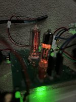
The amp sounds very loud and muddy. No treble at all, just bass and mids.
The bias control is doing nothing, I go from one end to the other and doesn't change a bit.
I looked at the valves and they seem a bit to red for me. Are they red-plating ? I am afraid that I am pushing them too hard.
Please check the picture attached.
Cheers,
Pedro
Attachments
Just to add to the post above, since I cannot edit. Above I meant the tone control, not the bias. Anyway, the bias doesn't do anything either.
Can the valves be saturated and nothing can change the sound? One more thing, increasing the volume near the maximum, puts the amp in oscillation. Can a stability problem be the issue to the muddy sound?
Now, I am clueless. :-(
Cheers,
Pedro
Can the valves be saturated and nothing can change the sound? One more thing, increasing the volume near the maximum, puts the amp in oscillation. Can a stability problem be the issue to the muddy sound?
Now, I am clueless. :-(
Cheers,
Pedro
It's always hard to troubleshoot from a distance.
First it's wise to measure the DC current goings through the tubes.
Do this with a shorted input.
Second thought would be if the transformer is connected the right way?
If not, it's in feed forward mode, which might also describe the bad sound.
Next I would just disconnect the feedback resistor for now. See if it's still oscillating. Keep in mind that this will make the gain go much higher!
Do you mean, to short both pins of the guitar input, that is, short the input signal to ground?First it's wise to measure the DC current goings through the tubes.
Do this with a shorted input.
I think so. Does the order of the pins matter?Second thought would be if the transformer is connected the right way?
When I have the feedback resistor there, it oscillates from a given level of volume upwards.Next I would just disconnect the feedback resistor for now. See if it's still oscillating. Keep in mind that this will make the gain go much higher!
Without the feedback resistor it oscillates heavily at, let's say, 80% of volume and then from that point upwards the oscillation decreases.!??! :-|
Regarding the pictures, do they look ok or are the valves too red ?
Cheers,
Pedro
@pcardoso73
I mean the input of the guitar amp.
So connector signal input to GND. (or just short RLEAK1)
What do you mean with "order of pins" ?
But to explain in general, transformers can be connected in a different way yes.
One way it will give a non-inverter output, the other way will give an inverter output.
That being said, if you get oscillations without the 22kOhm feedback resistor, something else is going on.
What kind of oscillation frequency are we talking about?
Is it also oscillation without any signal (so signal input connected to GND)?
I think the bias bypass circuit is not implemented correctly btw.
Usually the bypass capacitor is just being switched, to control the amount of gain.
In this case just the bias (load lines) is being changed.
With such a low input signal, I doubt if you would hear much difference.
By order of the pins I mean, swapping the common terminal with the high voltage one, and/or in the secondary swapping the common with the 8ohm terminal.What do you mean with "order of pins" ?
I've replaced the cables connecting to the speaker and the oscillations with the 22kohm resistor are no longer there. Removing the feedback resistor will give a very loud high-pitched sound.What kind of oscillation frequency are we talking about?
You are right. I've corrected that, putting a 1kohm resistor in series with a 10k pot, keeping the cap there since I don't want to alter the ac gain.I think the bias bypass circuit is not implemented correctly btw.
The idea is to be able to change the bias point so we can go from a warm sound to a cooler one. But, you are right, it's doing very little. I want to move the bias point from, let's say, -0.5V to -2.5V but that's not happening. I can move the bias point just by 200mV or so.
Another problem, when I touch the volume control the signal goes from very loud and muddy, to quiet and bright.
To rule out a grounding problem I tried touching with the back of a screwdriver (plastic) and the problem is the same.
Attached is a sound clip. Please give a listen to it.
0 - 20s ; high pitch sound when volume is increased and no feedback resistor is present
20-50s ; I am touching the volume slightly and the sound goes from bright lower volume to muddy and high volume
51s - 1:02m ; sound without feedback resistor (high volume -> high pitched sound)
1:03 - end ;
.
Cheers,
Pedro
Attachments
I've returned to this project and everything is working. Believe it or not, replacing cables, soldering everything into the pcb solved all the oscillation problems.
I had thin cables connected to thicker cables and then connected to something else. Reducing the length of the cables and using solid core AWG24 did the trick.
The volume potentiometer died during the several experiments I did (I don't how I killed it, but I did). I tend to solder and desolder over and over again the same components project after project and maybe because of this the components start failing. So, I've replaced both volume and tone pots by Alpha pots and the amp is now working as it should. The feel of the pots is so much better. No noise, vibration or any other problem that I had with the others.
The only thing I would like to tackle is to get rid of much of the bass. The amp is really bassy. I am feeling tempted to experiment a bit and put a very small cap across the feedback resistor and the degeneration resistor of the first stage. Let's say 470pF (just because I have those).
I had an idea (stupid maybe): what if I put a potentiometer connected as variable resistor, between the first stage (after the output cap) and the grid of the second and across it a 470pF capacitor. Wouldn't this help me reducing the bass? I have a 500kΩ pot around, so it should be enough for this...
Bottom line the amp works flawlessly, doesn't oscillate (even a max volume) and when cranked I get sweet distortion. It's loud for it's size (around 2W into a 12''Eminence speaker driver). On the negative side, it is too bassy.
Cheers,
Pedro
Start with the input stage bypass and coupling capacitors. Putting potentiometers in series with caps is also an option (used by Seymour Duncan Twin Classic) as tone pots.The only thing I would like to tackle is to get rid of much of the bass.
Once again, I defer to Rob Robinette who has a wonderful explanation of the many ways to voice an amp. Read it.
In fact, read everything he has written
Thanks for the reply.
To me, Rob Robinette and the Valve Wizard are the best resources on the internet on how to design valve amplifiers.
To be honest, I read a lot from Rob's website about several amplifiers, but never the voicing article (I am starting to read it now).
I will, first, decrease the value of the cathode bypass cap from 10uF to 100nF or 220nF and check if I am happy with it.
Cheers,
Pedro
On asking about a mosfet phase inverter, I used a IRF820, IRF830 and others work as the stage has 100% NFB. The mosfet fits in the connector as shown. You would not want the wires to be this long, a grid stopper resistor (oops, gate stopper?) should be close to the device, inline with the wire at the connector base? I also mounted it on a piece of perfboard. The center pin is connected to the tab and I used it electrically. The board has the bias resistors but not the ones on the source and drain. This would drop in a board with plate and cathode resistors or put them on the perfboard.

Yes there is a short at the output stage cathode resistor. Copy and paste, rearrange, good done. Or so you think.

Yes there is a short at the output stage cathode resistor. Copy and paste, rearrange, good done. Or so you think.
Last edited:
You can use a LND150 as well in that position. You have to be a bit more aware of the power dissipation.
Because of the high local NFB, this means the added distortion or tonal impact is very low (relatively speaking)
I use more or less this exact schematic for so many applications. Really simple and straightforward. Only blocking/nipple distortion can sometimes be a problem.
I think this can be fixed with some diodes.
Last edited:
No it's a problem that comes with the cathodyne type phase inverter.Is blocking/nipple distortion a problem with mosfets?
see:
http://www.valvewizard.co.uk/cathodyne.html
With a triode or LND150 (depletion mode fet), you can prevent this happening by adding some diodes to clamp the grid-cathode (or gate-source) voltage.
I have been simulating this with LTSpice with something like a IRF830, but it doesn't seem to really work in that case.
Last edited:
Startling, isn't it?...The amp is outputting an insane volume. I wasn't expecting this ....
<snip>
I've never thought that 3.5W could be this loud, but this thing rocks !!!
E-guitar speakers tend to be very efficient. OEM speakers often have sensitivity in the vicinity of 92 dB @ 1 watt @ 1 metre, while particularly sensitive aftermarket ones can top 100 dB @ 1 W @ 1 metre.
3.5 watts is +5.4 dBW, which we can add to the speaker sensitivity to calculate the SPL from that speaker. That means a speaker with 92 dB sensitivity driven by 3.5 watts will scream out over 97 dB SPL (at one metre distance in an anechoic room.) It will be even louder indoors. Yikes!
If you feed 3.5 watts into that aftermarket speaker with 100 dB sensitivity, you get an SPL of over 105 dB in an anechoic room - and well over that in a typical room.
For reference, a typical home vacuum cleaner has a typical loudness of about 70 dB @ 1 metre. That means it would take about five hundred vacuum cleaners, all screaming away at once, to reach 97 dB SPL!
In other words, with a 92 dB sensitivity speaker, the "little" 3.5 W guitar amp at full blast is as loud as five hundred vacuum cleaners.
The first time I did a calculation along these lines, I was convinced I must have made some enormous mistake, but multiple re-calculations eventually convinced me there wasn't one.
Hearing damage definitely occurs for sustained exposure to SPL levels above 85 dB, so either 97 dB or 105 dB SPL will, quite literally, damage your hearing over time (and not that much time). Longer and louder exposure will worsen the resulting hearing loss and may cause other unpleasant medical conditions including tinnitus.
It's hard to reconcile this with the common recommendation that you need at least a 40w guitar amp to play live gigs on stage, or with the fact that 100 watt and even 200 watt tube guitar amps were built and used live "back in the day". Most guitarists who used these did end up with hearing damage, sadly, but unsurprisingly.
After finding out that my 15-watt Fender Superchamp XD was ear-shatteringly loud in my home back in 2010, I was advised online that a 5-watt Champ would be much more appropriate for my purposes. No, it was ear-shatteringly loud in the store, so clearly 5 W was too much power.
I then designed and built a 2-watt tube amp using a pair of little 6AK6 pentodes from the era of tube radios - it was fine in a music jam setting, but much too loud in my apartment.
It was only after that that I finally did what I should have done back in 2010: I sat down with a spreadsheet and did some SPL calculations similar to the ones earlier in this post. That led me to the realization that a few milliwatts of power are all you need in a guitar amp for living-room use, particularly if you live in an apartment, as I do.
A few years ago I designed and built a roughly 0.2 watt (yup, around 200 mW) tube guitar amp - and that was about the right loudness for apartment use when plugged into the stock speaker in my '65 Princeton Reverb reissue. Well, it was about right for clean tones - but still too loud for heavily overdriven tones! Two tenths of a watt!
For me, this issue of excessive loudness has been a persistent thorn in my side when dealing with tube guitar amps. A good tube guitar amplifier sounds wonderful - but only when turned up to nearly full output power, which, for me, is usually too loud. But turn down the SPL, and the tube magic goes away.
-Gnobuddy
Hi,
Thanks for this detailed reply.
I am using a 12''eminence speaker driver, which has a 100dB SPL.
In fact, the SPL of the speaker is super important in the perceived volume. Most people (common users) don't understand the importance of the speaker and look only at the amp's wattage.
When I was a kid, I bought a Marshall Valvestate 8080, which I thought was the minimum to have a loud sound (80W) . In reality, I couldn't pass from 1/4 of the volume since it was way too loud !
Like you, I did an amplifier which has "only" 400mW of power and it is loud (through my 100dB Eminence). Now, I can go in the opposite direction, buying a less sensitive speaker and, at the same time, I can get a smaller one. (6'' or less).
It's a fun fact that we can adjust the volume just by changing speakers while keeping the same amp.
Cheers,
Pedro
Thanks for this detailed reply.
I am using a 12''eminence speaker driver, which has a 100dB SPL.
In fact, the SPL of the speaker is super important in the perceived volume. Most people (common users) don't understand the importance of the speaker and look only at the amp's wattage.
When I was a kid, I bought a Marshall Valvestate 8080, which I thought was the minimum to have a loud sound (80W)
. In reality, I couldn't pass from 1/4 of the volume since it was way too loud !Like you, I did an amplifier which has "only" 400mW of power and it is loud (through my 100dB Eminence). Now, I can go in the opposite direction, buying a less sensitive speaker and, at the same time, I can get a smaller one. (6'' or less).
It's a fun fact that we can adjust the volume just by changing speakers while keeping the same amp.
Cheers,
Pedro
I see. Very efficient indeed. Yes, agreed, that speaker is going to be very loud even at small power inputs!pcardoso73 said:I am using a 12''eminence speaker driver, which has a 100dB SPL.
Since we know hearing damage will occur at SPL levels above 85 dB, it's interesting to calculate the power input needed to produce 85 dB SPL from your very sensitive Eminence speaker.
85 dB (the target SPL) is 15 dB less than 100 dB (the SPL for 1 watt).
This means the necessary power (to produce 85 dB SPL) will be 15 dB less than one watt, or (-15) dBW.
Here's where things get really interesting: (-15 dBW) works out to 0.0316 watts, or 31.6 milliwatts!
So, on paper at least, any sustained audio power greater than about 30 milliwatts into this Eminence will result in sufficient loudness to potentially cause hearing damage.
Your "little" 3.5 watt amplifier has roughly one hundred times more power than this. It doesn't look so little now!
Going back in time several decades, there were plenty of tube radios with output power in the range of a watt or two, using speakers far less sensitive than your Eminence - probably 10 or 15 dB less sensitive. Back then, those radios were designed and sold to be adequately loud for the entire family to listen to. In other words, two or three watts into an speaker with 85 dB sensitivity was plenty loud enough for the whole family to enjoy back then.
Because guitars don't put out continuous sine wave signals, particularly if you're playing with clean tone, in practice I found that I could use more power than the result of simple calculations like this. For clean guitar tones, I found I could use maybe ten times as much power. In other words, to my ears, a guitar amplifier rated at 300 mW RMS maximum output power would probably be all I would want for home use for clean guitar tone. That's how I ended up building the 200 mW tube amp.
Unfortunately, the problem I always encountered trying to use tube amps in my apartment was that once the gain is turned up and maybe an overdrive pedal added, the guitar dynamic range is heavily compressed, and the perceived loudness increases dramatically. With the gain turned up for overdrive, now 300 mW was too loud (for me, in my housing situation).
For me, this situation was resolved satisfactorily for the first time when I bought a Boss Katana 50 some years ago. The Katana has a 1-watt setting, but the crucial point is that all guitar tone is generated before the power amp, so you can turn down the SPL without losing much amp tone in the process. I was finally able to set both clean tone and overdriven tones to apartment-friendly loudness levels.
-Gnobuddy
- Home
- Live Sound
- Instruments and Amps
- Subminiature Fender Champ