EL91, EL95 and 6AK6 are all cute little output tubes.Do you think I could do a Champ sounding amp using a 12AX7 and a an EL91/95 valves, instead of subminiature? That is, can I get a 6V6GT kind of sound out of an EL91/95?
I think there is a lot more to an amp than just the output tubes to "make THE sound".
So I can't really answer the question what the 6V6 sound is to you, to be perfectly honest.
But I think these are all great little tubes to make a good sounding guitar amplifier.

In general, what I would try to do, is put as much on one layer as possible and keep the other layer as a very solid ground layer.Hi,
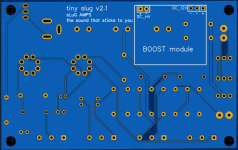
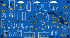
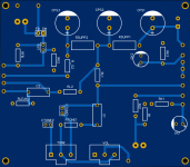
Can you, please, criticise my PCB layout and highlight errors and/or bad decisions that I have taken?
Cheers,
Pedro
It will be more puzzling, but I think it's doable here.
Otherwise, just go to four layer, it won't be much more expensive, and it is so much easier and better to route.
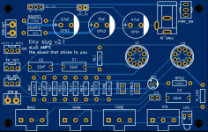
There are also a few things that I would do differently to make the routing a bit more neat.
Like swapping the position of RSUPP1 and 2, moving RL1 to the left, maybe above RSUPP1 etc etc.
That way you already need a lot less long tracks.
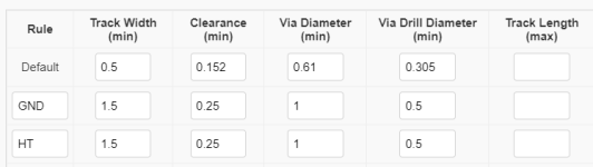
Other important thing, clearance needs to be MUCH bigger with these higher voltages!
Since it's a secondary voltage (so not directly mains related) we don't have to go for full clearance, bit this is too small.
@b_force
Hi,
Thanks for your inputs.
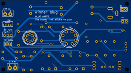
The ground plane covers completely the top layer of the PCB, that is where all components will be soldered.
The choice of separating the valves from the rest was to avoid the heat to affect other components, especially the electrolytic capacitors.
I can give it a try, but I doubt I will succeed.
Another big thing is noise and how to mitigate it during the PCB design phase.
My amplifier works fine and sounds great BUT, it has noise. Before connecting the the guitar cable, it exhibits 5kHz noise (switching power supplies?). After connecting the cable, 50Hz/100Hz noise appears.
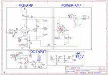
I am using a external 12V power brick (switching power supply), to supply a boost for HV and a buck to generate 6.3V for the heaters (maybe the heaters should be supplied with a linear regulator instead). I guess this plays a role in the noise too.
Regarding poor layout,how can the ground plane be used to improve the circuit noise performance. Does it make sense to split the large plane it two large squares and connect signal ground to one and power ground to the other? I don't have a "real" ground, since I am using a power brick, so I don't know.
Kind regards,
Pedro
Hi,
Thanks for your inputs.
That was what I thried to do. I placed the valves on one side and all the rest on the other.In general, what I would try to do, is put as much on one layer as possible and keep the other layer as a very solid ground layer.
The ground plane covers completely the top layer of the PCB, that is where all components will be soldered.
The choice of separating the valves from the rest was to avoid the heat to affect other components, especially the electrolytic capacitors.
I fully agree with this. The problem is that I have used an autorouter, since I am not capable of doing a manual signal routing with so many components.There are also a few things that I would do differently to make the routing a bit more neat.
Like swapping the position of RSUPP1 and 2, moving RL1 to the left, maybe above RSUPP1 etc etc.
That way you already need a lot less long tracks.
I can give it a try, but I doubt I will succeed.
Track width and separation was one of my main concerns and I've just made the width of the tracks 3 or 4 timeswhat the manufacturer suggests.Other important thing, clearance needs to be MUCH bigger with these higher voltages!
Since it's a secondary voltage (so not directly mains related) we don't have to go for full clearance, bit this is too small.
Another big thing is noise and how to mitigate it during the PCB design phase.
My amplifier works fine and sounds great BUT, it has noise. Before connecting the the guitar cable, it exhibits 5kHz noise (switching power supplies?). After connecting the cable, 50Hz/100Hz noise appears.
I am using a external 12V power brick (switching power supply), to supply a boost for HV and a buck to generate 6.3V for the heaters (maybe the heaters should be supplied with a linear regulator instead). I guess this plays a role in the noise too.
Regarding poor layout,how can the ground plane be used to improve the circuit noise performance. Does it make sense to split the large plane it two large squares and connect signal ground to one and power ground to the other? I don't have a "real" ground, since I am using a power brick, so I don't know.
Kind regards,
Pedro
Autorouters very very rarely come up with good results.I fully agree with this. The problem is that I have used an autorouter, since I am not capable of doing a manual signal routing with so many components.
I can give it a try, but I doubt I will succeed.
I think you will succeed
")
Most of the time it's actually using a lot of common sense and some logic, as well as putting your best puzzling hat on!
Just start with moving things, try to make tracks as short and tight as possible and just move from there
It will take a while in the beginning, but definitely will get better with more experience
The track width you're using now is fine, 1mm or so is in general enough for tubes amplifier.
Just the clearance to GND has to be much bigger.
@b_force
The amp sounds loud and amazing, but I can't get rid of the mains hum (despite being very low in volume) and with the volume in the middle or max, there is a combination of the bias position plus the tone position that makes it oscillate and hiss and it's not everything maxed. Strange thing....
The amp sounds loud and amazing, but I can't get rid of the mains hum (despite being very low in volume) and with the volume in the middle or max, there is a combination of the bias position plus the tone position that makes it oscillate and hiss and it's not everything maxed. Strange thing....
Normally using an oscilloscope.
These days you can also try to just use an audio interface for it as well.
If you only have a multimeter.
When connected correctly, feedback would give less gain compared to having no feedback.
So disconnecting the feedback loop, in your case I see that you have a switch for it.
When connected incorrectly, you will get more gain.
Measure frequency around 1kHz or so.
Actually, I have one of those scopes that you can connect to the PC and has many functions built in, which I've got recently and need a good reason to try it properly. I guess I have one now.
https://www.analog.com/en/design-ce...uation-boards-kits/ADALM2000.html#eb-overview
https://www.analog.com/en/design-ce...uation-boards-kits/ADALM2000.html#eb-overview
This message will go on both threads I have opened, so I can capture people that are only in one of them.
To thank you all for your support and sharing your knowledge with me, which gave me countless hours of fun, I would like to send you for free one PCB of one amp that you would like to try yourself.
I have basically two amps:
1 - Based on Fender Champ (Winner Slug)
2 - And a very low-power push-pull (Tiny Slug) based on the Superfly.
I can send you the PCB for free. Just pick one.
If you decide to build one, please give me your feedback: good, bad, so-so, garbage!
Have fun and Happy Easter.
Kind regards,
Pedro
Attachments
Maybe I'm too late for this thread,
but why not use power the heaters in series directly from the 12V?
Another thing I like to do to help with noise is keep the paths short.
Heaters could be offboard, so that you can twist the wires. Theoretically they should null their own noise that way.
Another thing is to use a ground plain surrounding the paths. It helps create a shielding effect, since it reduces the are which the noise will spread.
https://oxeltech.de/wp-content/uploads/2021/05/Stray-Capacitance-in-PCB-768x468.webp
@Thomasha I was going to do that but, sometimes, if I want to use a slightly different valve, the voltage across each heatter won't be the same. This way I am sure that I am forcing 6V to each one of them.
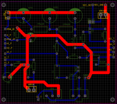
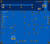
I did a new PCB and, as you suggested, I've kept the heater's connections off the PCB.
I removed the valve sockets and pulled the pins to the periphery.
All signal connections are in one side of the board and ground on the other.
Now, of course I have a problem.
I split the ground into 2 : signal and power ground, but the only ground reference, comes from the power supply (laptop adapter).
I am using the negative of the supply as power ground. But, where do I connect the signal ground? At this point they are all connected to the copper plane , so all of them are at the same potential, but this is not connected to any kind of ground.
Attached, you'll find my new layout.
RED -> Signal ground and Power ground
BLUE -> Signal
By the end, instead of routing ground as you can see from the the pcb_drawing.png file, I just added a "ground" plane for signal.
Is this layout any better? Any ideas, comments,....?
Kind regards,
Pedro
Attachments
- Home
- Live Sound
- Instruments and Amps
- Subminiature Fender Champ