Looks great - I like what you did with the legs supporting the horn. The paint and finisn look great too.

Thanks X. The legs are secured to a mounting pieces that are connected to M6 screw holes what I made for the spikes. Not the most robust but quite ok for home setup. Also much easier to lift the heavy bastards on and off the tapped horn.
X, I have been thinking to possibly make some filling plugs for the front chambers of the Deltalites. Could you simulate (if you still have the script) at some point how the Akabak predicts the changes in FR and phase if the front chamber is reduced from ~4 litres to 3, 2 or even 1 litres? No hurries.
Sure, not a problem. Give me a few days. I guess you are looking to extend the upper cutoff. I can't remember if you actually measured the volume and that is what I used last? If you haven't done so, please do using dry rice or beans. Or line with a plastic sheet and use water.
Sure, not a problem. Give me a few days. I guess you are looking to extend the upper cutoff. I can't remember if you actually measured the volume and that is what I used last? If you haven't done so, please do using dry rice or beans. Or line with a plastic sheet and use water.
I think you used the correct one in the last simulation, the volume was measured here: http://www.diyaudio.com/forums/subwoofers/258706-study-dipole-cardioid-bass-horn-25.html#post4018053
Last edited:
I think you used the correct one in the last simulation, the volume was measured here: http://www.diyaudio.com/forums/subwoofers/258706-study-dipole-cardioid-bass-horn-25.html#post4018053
Legis,
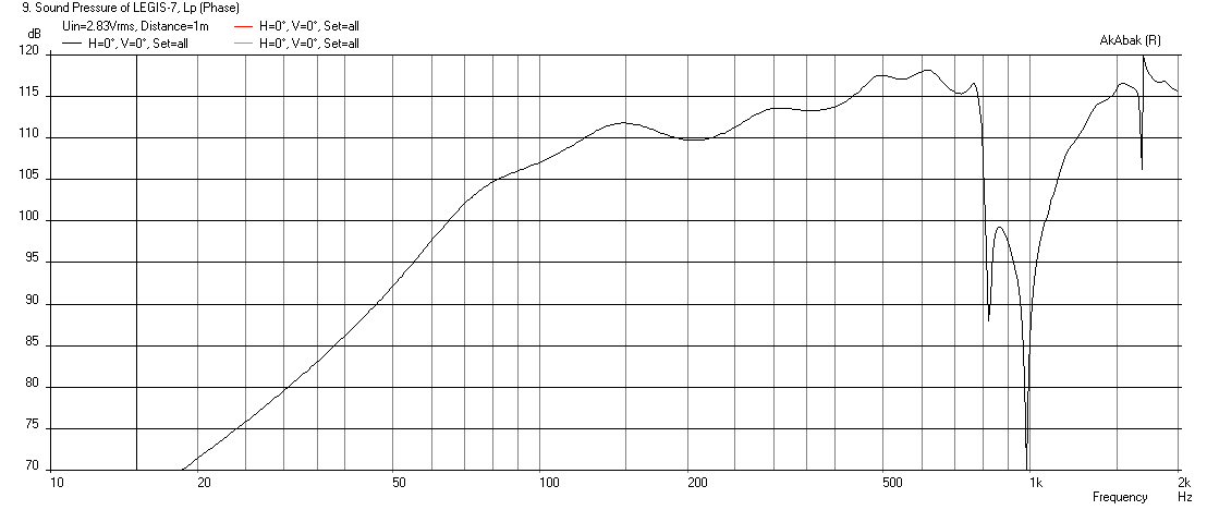
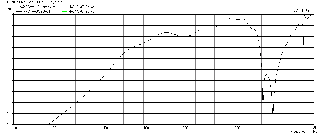
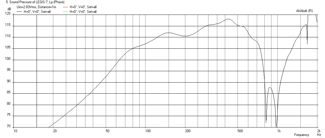
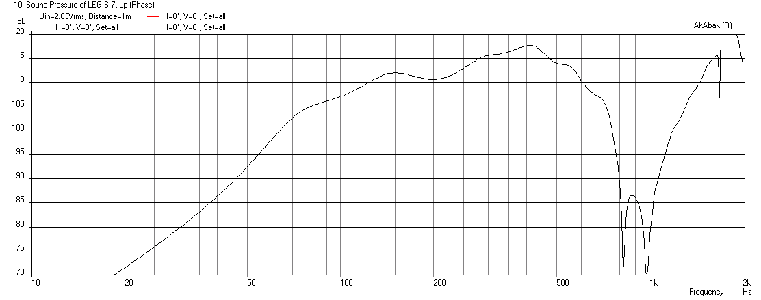
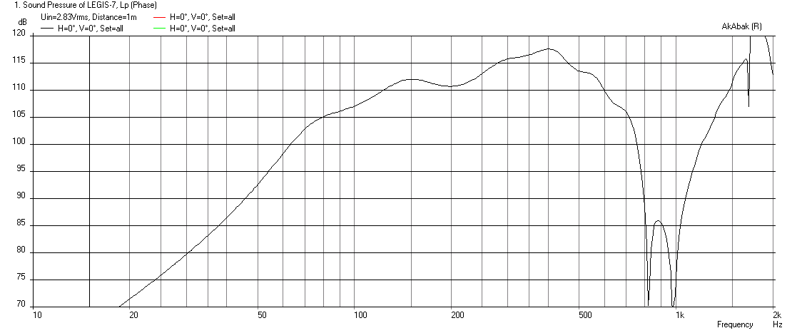
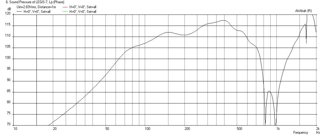
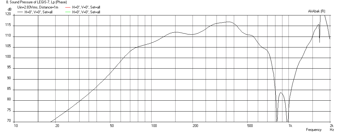
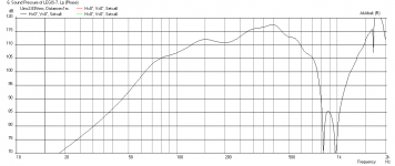
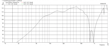
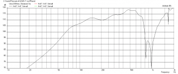
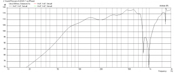
I forgot all about that - but now remember how you used rice. The last sim I ran for you I think I used 3.75 liters for the volume which includes the spacer. Here are the sims for the driver front chamber volume ranging from 0.5 liters to 5 liters:
0.5 liters:
1.0 liters:
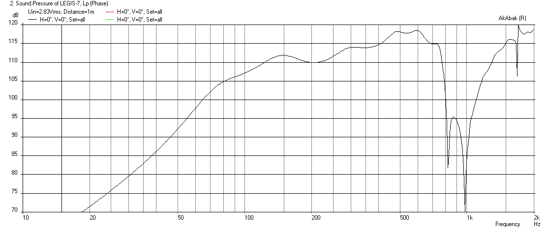
1.5 liters (this gets my vote as a nice option for higher freq extension to 700Hz if you build a volume filler insert):
2.0 liters:

3.0 liters:
3.5 liters:
3.75 liters (actual volume as-built):
4.0 liters:
5.0 liters:
Going from 3.75 liters to 1.5 liters is do-able I think as you are looking at about cutting the volume by about 2/3rds. Discs of foam core glued together would work, as well as discs of XPS (extruded polystyrene) home insulation pink foam sheathing,
Attachments
-
 Legis-7-0.50-liter.png15.4 KB · Views: 583
 -
 Legis-7-5.00-liter.png15 KB · Views: 570
 -
 Legis-7-4.00-liter.png15.6 KB · Views: 572
 -
 Legis-7-3.75-liter.png35 KB · Views: 566
 -
 Legis-7-3.50-liter.png15 KB · Views: 574
 -
 Legis-7-3.00-liter.png15.7 KB · Views: 565
 -
 Legis-7-2.00-liter.png15.5 KB · Views: 713
 -
 Legis-7-1.50-liter.png15.5 KB · Views: 578
 -
 Legis-7-1.00-liter.png34.9 KB · Views: 579
Last edited:
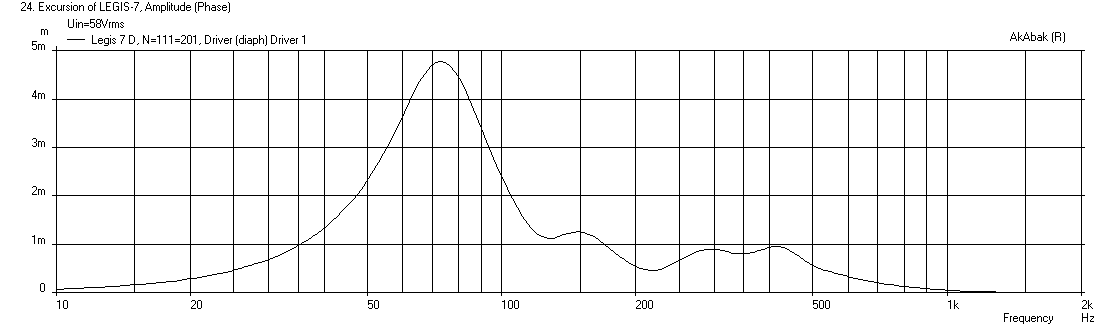
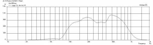
In case you ever wondered what your horn can do if pushed to max voltages, using a -12dB/oct HPF at 95Hz and a -24dB/oct LPF at 950Hz, it takes 58V to hit 4.8mm xmax.
Cone displacement at 58 volts:
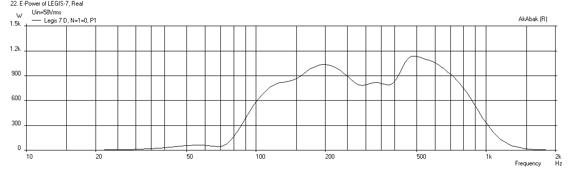
Electrical power input:
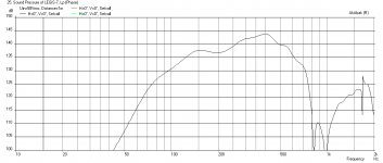
SPL at xmax:
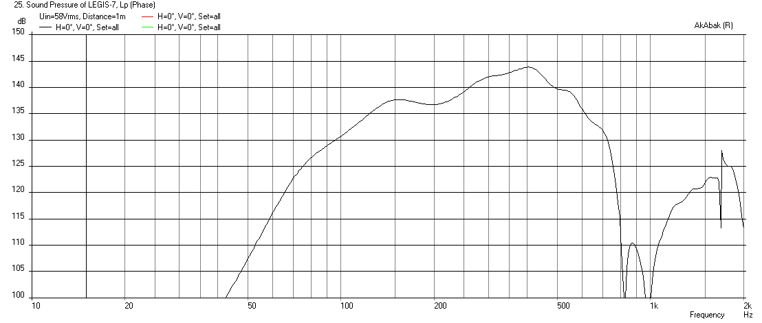
That is pretty loud, I mean like, stadium loud.
Cone displacement at 58 volts:
Electrical power input:
SPL at xmax:
That is pretty loud, I mean like, stadium loud.
Attachments
Thank you X for the sims once again!
I can use them now without any electrical filtering with good reults but it seems that it could/would be better with ~1-1.5 litres smaller front chamber. That reduction in chamber volume does not seem to steepen the xo slope too much/at all but extends the response somewhat higher what I'm looking for. Propably could be used with current settings, but the xo point (500Hz) could behave somewhat better.
I can use them now without any electrical filtering with good reults but it seems that it could/would be better with ~1-1.5 litres smaller front chamber. That reduction in chamber volume does not seem to steepen the xo slope too much/at all but extends the response somewhat higher what I'm looking for. Propably could be used with current settings, but the xo point (500Hz) could behave somewhat better.
Last edited:
X, I noticed that the first null appear to be at ~730Hz in my measurements instead of ~800Hz at your sims. The second null is on the contrary somewhat higher than you simulation predicts (~1170Hz vs. 1000Hz).
I understand that the ~1khz null comes from the injection port's distance from the apex, but what causes the ~800hz null and makes the reality differ from simulation?
I actually never accounted for the inner horn part of the 2446J driver itself to calculation how far away the injection port is from the "apex" of the horn, but it seems that the null is still higher. Odd. The center of the injection port is actually around ~21cm away from the "real apex" and the furthest part of the port is around ~26,5cm. Maybe the inner horn of the driver itself is too "tight" and the big radiating area of the Deltalites see it as very resisitive path and the waves don't travel there much at all so it's "invisible".
I understand that the ~1khz null comes from the injection port's distance from the apex, but what causes the ~800hz null and makes the reality differ from simulation?
I actually never accounted for the inner horn part of the 2446J driver itself to calculation how far away the injection port is from the "apex" of the horn, but it seems that the null is still higher. Odd.
The center of the injection port is actually around ~21cm away from the "real apex" and the furthest part of the port is around ~26,5cm. Maybe the inner horn of the driver itself is too "tight" and the big radiating area of the Deltalites see it as very resisitive path and the waves don't travel there much at all so it's "invisible".Quick test does not impress. I simply put 3 wooden "pucks" (total reduction around 0,5 litres per chamber) to front chambers with 2-sided tape. They are placed there from th injection holes, so the placing is not optimal. For some reason sensitivity went down a notch, initial low pass filtering increased slightly (also phase turns more at xo freq and the filtering of HF got worse). So exactly the opposite I'm looking for!
Red is the original, blue is the slightly filled front chambers.
So exactly the opposite I'm looking for!Red is the original, blue is the slightly filled front chambers.
An externally hosted image should be here but it was not working when we last tested it.
Quick test does not impress. I simply put 3 wooden "pucks" (total reduction around 0,5 litres per chamber) to front chambers with 2-sided tape. They are placed there from th injection holes, so the placing is not optimal. For some reason sensitivity went down a notch, initial low pass filtering increased slightly (also phase turns more at xo freq and the filtering of HF got worse).
Red is the original, blue is the slightly filled front chambers.
An externally hosted image should be here but it was not working when we last tested it.
That is strange - I wonder if it may have something to do with how smooth the airflow is inside the cavity. Did your pucks create some weird airflow pattern?
That is strange - I wonder if it may have something to do with how smooth the airflow is inside the cavity. Did your pucks create some weird airflow pattern?
I would know, propably. But they were not that far of where I would put them. Since I have the injection port located at the perimeter of the cone, I'm afraid the filler pieces are always somewhat "in the way".
My biggest fear is that I loose the capability to play them without any electrical crossover, current setup gives very good acoutical filtering. If it ain't broken...
On the other matter, Truextent beryllium mebranes came in last week. I haven't installed them both yet, just one. I'm in middle of bracing the tapped horns' mouths a little, after I finish it I can install both membranes and have a listen!
An externally hosted image should be here but it was not working when we last tested it.
An externally hosted image should be here but it was not working when we last tested it.
Got the tolerances "ok" for both horns. Had to modify the throats and the drivers' fitting pieces a little. Beryllium membranes shoot a flat or mildly spherical minimum phase wavefront, which is MUCH more sensitive to all very minor discontinuities and imperfections in the throat than titanium membranes!
Truextrents have very smooth freq response in hearing range since the first dome resonance is pushed over 20khz. Their polymer surround seems to have lower THD (almost a decade) at low band than metal surrounds and HF does not have any H2 spikes like the ribbed membranes had. Allround better performer. I also like their sound signature. Non-fatiqueing, hyper clear and micro-resolutive at all SPLs, somewhat more "fast" at transient attacks. Brass instrument, high-hats etc. metallic instruments have very "true" tonal palette (for which reason I like metallic membrane compression drivers in general).


Truextrents have very smooth freq response in hearing range since the first dome resonance is pushed over 20khz. Their polymer surround seems to have lower THD (almost a decade) at low band than metal surrounds and HF does not have any H2 spikes like the ribbed membranes had. Allround better performer. I also like their sound signature. Non-fatiqueing, hyper clear and micro-resolutive at all SPLs, somewhat more "fast" at transient attacks. Brass instrument, high-hats etc. metallic instruments have very "true" tonal palette (for which reason I like metallic membrane compression drivers in general).
@ Legis
Truextrent beryllium
What's the chart depicting ?
Oh sorry forgot to add description (and for the funny typo
). The chart is the 0deg response of the both horns at the horns mouth. Measured by hanging the mic on the mouth like I have done previously. The HF slopes off faster this way by not directing the mic to the throat.I was asked via private message about the push-pull tapped horn's folding and I made a crude picture showing most of the dimensions to the rest of the interested.
This is pretty much the script I have used to sim it, here showing Eminence Sigma Pro 18 woofers. Other S1-S2etc. lenghts I have used are 27cm, 150cm, 80cm, 27cm. The folding seems to work good with many drivers propably due to long pipe section in the beginning.
Response ot the ready horns can be taylored quite much by damping and/or restricting the mouth area. It lowers the tuning but seems to affect very little to the sensitivity, at least when adding damping. Lowering the tuning by making the mouth smaller (which also transforms the front chambers to bandpass chambers) affects the sensitivity more, but not that bad even when restricting the area to ~25% from original. I think they could be tuned to quite low tuned "HT tapped horns" with enough damping and mouth size restriction if one wants the best LF sensitivity and extension.
I recommend bracing at least the back wall and the mouth. Mouth is hard to brace as one installs the drivers from the mouth, but inreasing the wall thickness from 15mm to 30mm works good. One could also add some metal braces and/or use some heavy duty speakers grill intelligently to brace the mouth. After finishing the horns I made partial plywood "T-braces" to the mouth's wall showing in this picture, adds bracing but does not weight too much.
Regarding the crossover, I find that these tapped horns sound good basically with any electrical xo, and even without any electrical crossover (with just the acoutical xo) or with 1st order low pass filter - as I currently use them. Adding damping material to mouth steepens the acoustical crossover. One could propably make them work without electrical filtering in a "purist" passive filtered setup. 10 watts per horns means very loud SPL, and even hard clipping transistor amps (TA2024) sound almost like "soft clipping" due to acoustical crossover/bandpass of the tapped horn, which is a very nice feature when playing with small amps like I'm curretly doing.
I don't recommend copying anything, including my horns, exactly 1:1, but taking ideas and tweaking them to even better execution and results and share them.
An externally hosted image should be here but it was not working when we last tested it.
This is pretty much the script I have used to sim it, here showing Eminence Sigma Pro 18 woofers. Other S1-S2etc. lenghts I have used are 27cm, 150cm, 80cm, 27cm. The folding seems to work good with many drivers propably due to long pipe section in the beginning.
An externally hosted image should be here but it was not working when we last tested it.
Response ot the ready horns can be taylored quite much by damping and/or restricting the mouth area. It lowers the tuning but seems to affect very little to the sensitivity, at least when adding damping. Lowering the tuning by making the mouth smaller (which also transforms the front chambers to bandpass chambers) affects the sensitivity more, but not that bad even when restricting the area to ~25% from original. I think they could be tuned to quite low tuned "HT tapped horns" with enough damping and mouth size restriction if one wants the best LF sensitivity and extension.
I recommend bracing at least the back wall and the mouth. Mouth is hard to brace as one installs the drivers from the mouth, but inreasing the wall thickness from 15mm to 30mm works good. One could also add some metal braces and/or use some heavy duty speakers grill intelligently to brace the mouth. After finishing the horns I made partial plywood "T-braces" to the mouth's wall showing in this picture, adds bracing but does not weight too much.
An externally hosted image should be here but it was not working when we last tested it.
An externally hosted image should be here but it was not working when we last tested it.
Regarding the crossover, I find that these tapped horns sound good basically with any electrical xo, and even without any electrical crossover (with just the acoutical xo) or with 1st order low pass filter - as I currently use them. Adding damping material to mouth steepens the acoustical crossover. One could propably make them work without electrical filtering in a "purist" passive filtered setup. 10 watts per horns means very loud SPL, and even hard clipping transistor amps (TA2024) sound almost like "soft clipping" due to acoustical crossover/bandpass of the tapped horn, which is a very nice feature when playing with small amps like I'm curretly doing.
I don't recommend copying anything, including my horns, exactly 1:1, but taking ideas and tweaking them to even better execution and results and share them.
Thanks for the detailed plans Legis. Good to know about constricting the mouth for improved bass extension. That is similar to the ML Transflex sub that was discussed earlier. I love your wood work and craftsmanship. How do you make it look like factory made furniture? It is so smooth and neat. Just beautiful.
10 watts is too much SPL. lol.
10 watts is too much SPL. lol.
Thanks for the detailed plans Legis. Good to know about constricting the mouth for improved bass extension. That is similar to the ML Transflex sub that was discussed earlier. I love your wood work and craftsmanship. How do you make it look like factory made furniture? It is so smooth and neat. Just beautiful.
10 watts is too much SPL. lol.
Thanks X. Enough wood filler + textural finish paint roller and satin/half gloss paint... makes things easier.
Here is random old measurement which I made when i was testing the mouth damping, ie. adding the yellow foam pieces to the mouth. They are measured close to mouth, without any xo or eq. The low bass sensitivity increases the more you put in damping/flow resistance to some point. Seems to affect very little the pass band sensitivity otherwise, middle bass does not lose sensitivity much, so it's almost pure win-win.
An externally hosted image should be here but it was not working when we last tested it.
An externally hosted image should be here but it was not working when we last tested it.
And here is the effect of mouth size restriction which I also tested with a quick hack setup some time ago. (Both measurement are from the time before I braced the mouths).
I think this is measured from longer distance (than almost at the mouth), can't remember the specifics or if some XO/EQ was used. But I planned to test these mouth-related topics again in the future.
An externally hosted image should be here but it was not working when we last tested it.
An externally hosted image should be here but it was not working when we last tested it.
I think by combining the two above methods the path lenght could be made effectively much longer than it is with completely open mouth (ie. ~280-300cm). Different tunings could be beneficial for HT/music.
Damping the mouth increases the "fullrange SQ", restricting the mouth size decreased it in my hack-test if no damping were used inside the front chambers.
Right now I'm using them without any damping/size restriction in the mouths. 1st order low pass or completely filterless setup is totally doable even this way, they sound good a) by themselves and b) as a part of the whole system imo. It's quite "ideal" and easy starting point if every band of the speaker sounds relatively good just by itself "as-is", ie. without any electrical response tayloring.
Last edited:
Small update.
I encourage everyone to try slight damping in the throat chamber/front chamber of mid woofers. I tested it in my synergies by putting 10mm thick absorping (quite dense, ~100kg/m3) plastic foam mat in front of the 15" midwoofers cones. It works really good. It increases the acoustical low pass somewhat, takes care of HF resonances (beyond the pass band) and also makes the pass band sound clearer and more "non-resonant". Especially noticeable in my application since I don't use electrical LPF with midwoofers, but I can hear difference also with LPF filter engaged.
I'm sorry I don't have measuring equipment in working condition right now.
An externally hosted image should be here but it was not working when we last tested it.
Last edited:
- Status
- This old topic is closed. If you want to reopen this topic, contact a moderator using the "Report Post" button.
- Home
- Loudspeakers
- Subwoofers
- Study of a Dipole/Cardioid Bass Horn