SR50 pcb in progres
It was tested, the problem is dc offset too high. First test about 150 mV and go down about 70 mV.
What should to be change?
Regards
Hai Mas Reski,It was tested, the problem is dc offset too high. First test about 150 mV and go down about 70 mV.
What should to be change?
Regards
do you use TL071 for servo?
If we use SanKens for output transistor that maybe happen
it is oscillating

try add base stopper on it, but one 20pF cap solve the problem in my SanKens SR200
this from post #1250

Maybe it is same for SR50
Regards
Last edited:
Hai Mas Reski,
do you use TL071 for servo?
If we use SanKens for output transistor that maybe happen
it is oscillating
try add base stopper on it, but one 20pF cap solve the problem in my SanKens SR200
this from post #1250
Hi Bli...
I'm using TL071 and LF411 but still the same.
Thank's for your information, I'll try with Toshiba on output first and than try to add another cap for compensation if the problem still the same.
Hi Bli...
I'm using TL071 and LF411 but still the same.
Thank's for your information, I'll try with Toshiba on output first and than try to add another cap for compensation if the problem still the same.
Today I try to remove dc servo and dc offset about 18 mV and set bias at 75 mA. The sound is really nice and heatsink just warm. I hope it still save for loudspeaker.
I think ,625VA transformer is big enough for single board of APEX SR200...Is not it??
What the AC output voltages ?
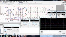
today I tried to simulate the SR200 using multisim software, I tried using a voltage 77VDC and try to power up to 500W with 4 Ohm load. I get THD at 0.062% and the low distortion. I'm still a beginner using this software and do not quite understand about the power amplifier, I need guidance especially to Mr. Power's Mile designing.
My question, when running the simulation value of the voltage at the red dot, for at the + value always increases until it reaches a peak at 500mV and the red dot part - always below the value of +. why not draw? if like this then? I do not really know
My question, when running the simulation value of the voltage at the red dot, for at the + value always increases until it reaches a peak at 500mV and the red dot part - always below the value of +. why not draw? if like this then? I do not really know
Attachments
Last edited:
I would think that using a simulation package for predicting maximum power is probably not going to be useful.
The Maximum power is limited by the supply voltage while the load is pulling down the supply and the current passing through from PSU to Load.
These two limiting factors can be more easily and accurately determined by measuring the amplifier.
The Maximum power is limited by the supply voltage while the load is pulling down the supply and the current passing through from PSU to Load.
These two limiting factors can be more easily and accurately determined by measuring the amplifier.
I will try to build SR800 by myself after documentation that I have and i will come back with the PCB and results.Last week i tried to fix my APEX H900 but without results.He work perfect until the stepping from Low rail to hi Rail,when the stepper is active on oscilo appear spikes and i don't like that.And on square wave form looks very very bad so i lef away the H900
Waiting for this.I will try to build SR800 by myself after documentation that I have and i will come back with the PCB and results.Last week i tried to fix my APEX H900 but without results.He work perfect until the stepping from Low rail to hi Rail,when the stepper is active on oscilo appear spikes and i don't like that.And on square wave form looks very very bad so i lef away the H900

Trying to repair amplifier..
Working on amplifiers with out schematic can be a pain because you have to sit and trace out the circuit point to point and we've all done that over the years plus knowing how a the circuit works such as tail input then vas/ bais then driver to o/p devices.. Plus it may have v- limiter in there!!!
Start off by checking round the input pairs plus show us a photo of the amp your working on.
I will try to build SR800 by myself after documentation that I have and i will come back with the PCB and results.Last week i tried to fix my APEX H900 but without results.He work perfect until the stepping from Low rail to hi Rail,when the stepper is active on oscilo appear spikes and i don't like that.And on square wave form looks very very bad so i lef away the H900
Working on amplifiers with out schematic can be a pain because you have to sit and trace out the circuit point to point and we've all done that over the years plus knowing how a the circuit works such as tail input then vas/ bais then driver to o/p devices.. Plus it may have v- limiter in there!!!
Start off by checking round the input pairs plus show us a photo of the amp your working on.
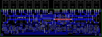
..... PCB ready , please someone check if it's correct layout . I will post in B&W the layout of PCB .
Schematic will follow soon .
Regards ,Alex
I can't find the schematic but it looks like the base ties to the output through 4R7 resistors?
- Home
- Amplifiers
- Solid State
- Studio Reference Amplifier