I mean 2 caps on the side(right & left) of my 3D preview. This caps are regards to C5, C6, C12, & C13 on apex schematic.
I saw Alex MM pcb adds 3 more 470uF caps onboard but don't know what it is for?
Anyway I will not do like that,
I will just add 2 100nF caps near the IC1 @+/- 15V to PGND
& one between PGND - SGND.
Still don't know what it is for
but I feel I need to do that.
Regards
I saw Alex MM pcb adds 3 more 470uF caps onboard but don't know what it is for?
Anyway I will not do like that,
I will just add 2 100nF caps near the IC1 @+/- 15V to PGND
& one between PGND - SGND.
Still don't know what it is for
but I feel I need to do that.
Regards
The purpose of using the 3 pairs of caps for me is particularly I just wanna use some parts that I have them for some time ago. ha ha ha (joking )...Now I want them work for me...
Considering to Mr. Alex MM's pcb, I am sure he did it on purpose, putting some caps on board... I have a lack of skill referring to that science. But looking at my experience building the 1st SR200 that sound very good (IMHO)...I think I will do the same for the 2nd SR200, use the same topology as the 1st one.
Regards,
Arif.
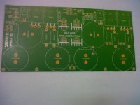
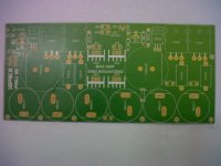
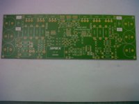
These are my new pcbs, some parts are available on my drawer.. I will try to install them soon. I hope I have spare time.
Nice PCB Mr. Arif Bravo
These are my new pcbs, some parts are available on my drawer.. I will try to install them soon. I hope I have spare time.
Nice PCBs, and dual TO220 diodes instead bridge rectifier...
Regards
Thank You mas Damanhuri...I am sorry, I went to bed early last night (OOT)...please send me an email..Nice PCB Mr. Arif Bravo
Nice PCBs, and dual TO220 diodes instead bridge rectifier...
Regards
Thank you so much Mr. Apex...
Could you please advice me the purpose of putting some 470 uf caps on boards. I just follow Mr. Alex MM's pcb design, referring to my experience building the 1st SR200 that sound very good (IMHO)...I feel there is an advantage doing that...
Many thanks.
Best Regards,
Thank you so much Mr. Apex...
Could you please advice me the purpose of putting some 470 uf caps on boards. I just follow Mr. Alex MM's pcb design, referring to my experience building the 1st SR200 that sound very good (IMHO)...I feel there is an advantage doing that...
Many thanks.
Best Regards,
Just use 2,2uF/100V.
Regards
Thanks for your guidanceJust use 2,2uF/100V.
Regards
@Arif Budiyanto & DAMANHURI
congrats bro, I wish your SR200 will be finished soon.
Don't forget to try with & without additional 470uF on board & let us know the diference.
Mas DAMANHURI if you don't mind please share your/our new design & we wiil check here
Best Regards
Thanks for your guidance
@Arif Budiyanto & DAMANHURI
congrats bro, I wish your SR200 will be finished soon.
Don't forget to try with & without additional 470uF on board & let us know the diference.
Mas DAMANHURI if you don't mind please share your/our new design & we wiil check here
Best Regards
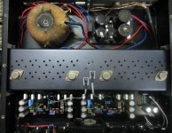
I will soon complete the SR200 and I'm making custom components of the 3D version of the pretty sight, I'll change the components of you that you have sent with a custom component that I created without changing position. I hope this week will be completed soon and I'll let you Jhon. for the addition of 470 I will try, and I would also make the original version of APEX. you are my good friends who always share their knowledge.
This design by Alex MM SR200 is still in the wiring. I hope there is no problem.
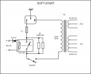
Nice work, use 150R/10W instead primary fuse for test.
Just use 2,2uF/100V.
Regards
Dear Mr. Mile S.
Thank you so much for your quick reply...
Bets Regards.
Arif
Thank you dear DAMANHURI, I am sorry yesterday I went to bed early, I was so tired..Nice PCB Mr. Arif Bravo
I can not wait to hear your amp works good...Bravo my friend!
Thank you dear DAMANHURI, I am sorry yesterday I went to bed early, I was so tired..
I can not wait to hear your amp works good...Bravo my friend!
no problem Mas Arif.
Nice work, use 150R/10W instead primary fuse for test.
I use a 50 VDC voltage. whether it is appropriate to the value of this resistance? where should I put this position to try detainees?
I use a 50 VDC voltage. whether it is appropriate to the value of this resistance? where should I put this position to try detainees?
Maybe you can put safety resistor instead of the fuse, I put safety resistor parallel with the fuse (I install the resistor under the pcb). It is easier for me whenever I want to change my amp's bias setting, just need to uninstall the fuse, set bias as I wanted, and install the fuse back on board. CMIIW...
It is better to follow Mr. Apexaudio's advice, use 150R/10W safety resistor
Best Regards
OK Thanks Mas Arif. I try
- Home
- Amplifiers
- Solid State
- Studio Reference Amplifier