May be take a look at the JBL EON 615. They use a special slot (see images) to adapt directivity of a 15''-woofer to a horn in a two-way.
A frontplate with aperture like JBL EON is different from "slot loading" I guess? Where's the turning point? https://jblpro.com/products/eon615

Karlson K-slot is sort of ancient curiosity for large fullrange drivers. https://www.diyaudio.com/community/...-behind-a-karlson-karlsonator-speaker.305631/

Karlson K-slot is sort of ancient curiosity for large fullrange drivers. https://www.diyaudio.com/community/...-behind-a-karlson-karlsonator-speaker.305631/
I think the easy answer is it doesn't need to be. Generally speaking the arrival times will lower be than cycle times of frequencies of a bass unit or low. Eq can manipulate the time to peak energy, which is equivalently important for transient qualityYou still have not explained how EQ could "fix" the multiple time arrivals from a bandpass chamber placed in front of a driver
Well, I'd regard this still as kind of slot-loading, as it has an effect on the woofers directivity and is intended to do so. I did not simulate this one, but I think the curvature of the 'slot' deals with the cavity resonances, i.e. minimizes them because of the curved shape of the 'slot'.A frontplate with aperture like JBL EON is different from "slot loading" I guess?
I'm sure the 'Karlson-slot' will broaden the directivity of the woofer as well.
Though these are not real slots in terms of a rectangular form, they still do the same in terms of modulting woofer directvity.
here's an unusual slot loaded design, made to mount on the wall up against the ceiling.
https://www.danleysoundlabs.com/products/sf1/

https://www.danleysoundlabs.com/products/sf1/
Yeah I bet that the shape of the slot in that JBL is varied to kind of distribute any i'll effects, for example cavity resonances. This would make the graphs little bit smoother looking, just like offsetting drivers to mellow out baffle diffraction related interference. I think they added the slot to have better match around crossover directivity wise both horizontal and vertical. Obviously, if this was some magic pill we would have slots on most speakers. It's fun try and think why they did that there and not with other products? anyone? Perhaps too subtle effect before trade-offs and not worth it.
I do not know what's the reasoning behind Karlson box and can only speculate. The characteristic aperture might be part visual appeal and part of marketing. Perhaps it was effort to reduce "beaming", while also avoiding too strong of a low pass / resonances, to better sound of a fullrange driver they used. I think there is could be some positive effect on directivity, or just getting more treble through floor to ears, something they listened on the shop and thought was fine. Anyone simulated Karlson box in BEM to see how it works out? Anyway, physics are still the same and all kinds of apertures and slots aren't that popular. While they might sound just fine, perhaps there is not enough benefit with cost or something. Reasoning like I've done here with few posts it's obvious to me there is no need for slots in home audio, unless there is great benefit. Acoustic low pass could be used to benefit, perhaps could help with c-c spacing as in MEH and perhaps something else
I do not know what's the reasoning behind Karlson box and can only speculate. The characteristic aperture might be part visual appeal and part of marketing. Perhaps it was effort to reduce "beaming", while also avoiding too strong of a low pass / resonances, to better sound of a fullrange driver they used. I think there is could be some positive effect on directivity, or just getting more treble through floor to ears, something they listened on the shop and thought was fine. Anyone simulated Karlson box in BEM to see how it works out? Anyway, physics are still the same and all kinds of apertures and slots aren't that popular. While they might sound just fine, perhaps there is not enough benefit with cost or something. Reasoning like I've done here with few posts it's obvious to me there is no need for slots in home audio, unless there is great benefit. Acoustic low pass could be used to benefit, perhaps could help with c-c spacing as in MEH and perhaps something else
Last edited:
A good example where simple VituixCAD simulation falls aparthere's an unusual slot loaded design, made to mount on the wall up against the ceiling.
https://www.danleysoundlabs.com/products/sf1/
View attachment 1307661
Last edited:
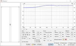
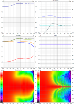
Here are some images of a slot loaded woofer I did some time ago. I was still learning abec and put the slot on the front mainly due to lack of skill with abec but it turned out to be quite good even without moving the driver closer to the slot exit and closing off the back, so I didn't bother

next, the polar maps (normalized)


the curves show its usable at least to 200 Hz


The driver is a Stereo Integrity 11" shallow mount subwoofer. Intended usage is to lay flat under an OB woofer and play through an end slot out the front.
next, the polar maps (normalized)
the curves show its usable at least to 200 Hz
The driver is a Stereo Integrity 11" shallow mount subwoofer. Intended usage is to lay flat under an OB woofer and play through an end slot out the front.
B&M use kind of slot-loading (they partially cover the front of their drivers, in some models combined with horn contours) in their products, e.g. here or here. However, I understand that this shifts to some kind of compression chamber for conus horn drivers. Just want to point out, that 'slots' are often used to broaden the coverage angle of horns - not exactly woofers though and a different frequency range.
B&M seems to use recessed mid drivers and we know that it makes strong diffractions... no loading effect of lows with that low recession either.
Loading or loss is semantics... baffle step is good example. If we agree that infinite baffle is the norm, all smaller baffles show 6dB loss of spl down low and 2-3dB step/loading just below first diffraction nulling. Slot loading is similar as well as horn loading - extra spl at certain range and loss above and below it (compared to infinite baffle) - bandpass filtering

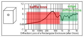
Loading or loss is semantics... baffle step is good example. If we agree that infinite baffle is the norm, all smaller baffles show 6dB loss of spl down low and 2-3dB step/loading just below first diffraction nulling. Slot loading is similar as well as horn loading - extra spl at certain range and loss above and below it (compared to infinite baffle) - bandpass filtering

Last edited:
Why did you tell us the size of the woofer in the slot but not the dimensions of the slot, when thats the more important figure???The driver is a Stereo Integrity 11" shallow mount subwoofer.
I've seen that before, thanks though.May be take a look at the JBL EON 615. They use a special slot (see images) to adapt directivity of a 15''-woofer to a horn in a two-way.
Acoustic low pass could be used to benefit, perhaps could help with c-c spacing as in MEH and perhaps something else
Yes, I want to keep the roundover on the horn mouth as intact as possible. Acoustic filtering of harmonics and c-c spacing was my main reason for wanting to try smaller apertures over the 10NW64's, and limit the vertical opening size.
This is with the 10NW64's in some angled recylcled boxes.
^ hi, nice example. Here is how to look at this stuff by eye, thinking with wavelength, and make simple quick simulation in brain so to speak 
As the slot in the woofer box is similar in size with the waveguide, they are likely best crossed over about at there, at wavelength where both the waveguide and the woofer box have (similar) effect on directivity. Now, looking at features of the slot the depth looks similar in size to the opening, which tells there is gonna be a reflection from apex of the slot delayed by distance from cone center to apex and back. Eyeballing the reflection is about similar distance late as size of the waveguide and the slot opening. All I see is reflection problems start at similar wavelength where crossover likely is at. This would mean the reflection affects sound around crossover frequency even if I do not know absolute sizes or what frequency the crossover would be at. I cannot quickly see what exactly a problem would look like in graphs, and it might not matter audibly that much, but it would be good to check out with measurement and perhaps try to listen whether it matters at all. Then you can evaluate whether the arrangement is worth it considering this possible trade-off (compared to just flat baffle for woofers).
The thing is, a multiway speaker needs a crossover which means multiple sound sources are emitting overlapping bandwidth. Since two physical objects cannot occupy same space at same time they necessarily are in each others close proximity and affect each other acoustically so there is always going to be some kind of interference no matter what. Fullrange driver doesn't save it either, since it's impossible to have an object be small and large at same time which means directivity would change with frequency + other issues. Perhaps not audible, but still as philosophical thing, how to think about this stuff. While some solutions are bit better than others, there isn't any perfect solution to this and it's always some kind of a trade-off how to arrange a loudspeaker physical structure. Objects have static size, while sound size (wavelength) is from huge to small at the same time.
Last edited:
Hi,Here are some images of a slot loaded woofer I did some time ago. I was still learning abec and put the slot on the front mainly due to lack of skill with abec but it turned out to be quite good even without moving the driver closer to the slot exit and closing off the back, so I didn't bother
View attachment 1307674
next, the polar maps (normalized)
View attachment 1307675 View attachment 1307676
the curves show its usable at least to 200 Hz
View attachment 1307679 View attachment 1307680
The driver is a Stereo Integrity 11" shallow mount subwoofer. Intended usage is to lay flat under an OB woofer and play through an end slot out the front.
you posted another one my simplification fails
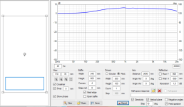
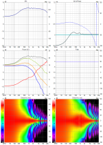
which was my point earlier -you only really need BEM if you want to see how high the slot can be used and want to be able to use it fairly hign. what's needed is a rule of thumb for the limit where simple vituix and HR sims can be trusted. First you have to do an HR sim to check and manage the bandpass effects and then, when converting from axisymmetric to rectangular, make sure slot dimensions aren't an appreciable fraction of a wavelength
BTW IIRC box was about 34 cm wide but only 50 cm deep
BTW IIRC box was about 34 cm wide but only 50 cm deep
Considering few examples here on this thread I think VituixCAD simplification is fine with following constrains:
- transducer is bigger than the aperture
- chamber has minimal volume, not much bigger than the volume in the cone
- aperture in front of the transducer
Last edited:
A good example where simple VituixCAD simulation falls apartHorizontal directivity is likely close, but vertical likely doesn't as it ignores the whole long waveguide that is inside the real device, transducer is smaller than the aperture in vertical plane. Also any resonances that likely happen, some sound reflects back to throat
View attachment 1307670 View attachment 1307669
Cool. Thx.
I was told by Danley folks when they presented it at a trade show, that the inspirational spark behind the design was a CBT.
I would think modeling would have to include the CBT-like curvature, the narrowing vertical slot, the reflex ports, and the mandatory corner mounting/loading.
But then again, I ain't no modeler!
- Home
- Loudspeakers
- Multi-Way
- Studies or papers on slot loaded woofer directivity?