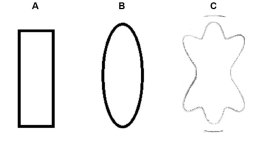
I've studied it a bit...
The directivity/dispersion/diffraction effect of the slot (slit) or round aperture can be calculated with relative ease, but the interaction due to the chamber volume and actual dispersion due to cone breakup of the woofer can not.
https://reference.wolfram.com/langu...AcousticWaveDiffraction.html.zh?source=footer
In other words, one could put the same 6" slot in front of two different 15" woofers equalized for the same on axis response and have different off-axis directivity for each.
The chamber imparts an acoustic band-pass low pass filter, with an upper peak followed by the LP.
The slot chamber resonance increases decay time compared to an open driver.
Depth, shape, surround, mass of the cone, location of the voice coil and dustcap all add to the complexity.
Thanks Art, assuming limited bandwidth for a woofer firing through a round aperture, operating out of breakup in the piston band, hoping the off axis is going to be well behaved.
I have some 10NW64's in recycled boxes configured similarly to Mark100's BMS loaded V-twin subwoofer build. I will wait for better weather to do some measurement outdoors off axis with the apertures I want to test clamped in place over the front of the boxes.
I have some 10NW64's in recycled boxes configured similarly to Mark100's BMS loaded V-twin subwoofer build. I will wait for better weather to do some measurement outdoors off axis with the apertures I want to test clamped in place over the front of the boxes.
The "V" directivity behavior shouldn't be any more problematic than the frequency response.I have some 10NW64's in recycled boxes configured similarly to Mark100's BMS loaded V-twin subwoofer build. I will wait for better weather to do some measurement outdoors off axis with the apertures I want to test clamped in place over the front of the boxes.
The "V" forms a short offset horn, boosting the upper mid range ~100-300Hz, response above that will be fairly peaky.
The Fulcrum US212 frequency response will give you a rough idea of what to expect from the "V" configuration:
Putting an aperture in front of the relatively large dual 10" "V" chamber will make it a 4th order bandpass, usable response may not even extend past the frequency where polar response would be (almost) omnidirectional.
The bandpass resonance increased decay time (ringing) will be more of a problem than directivity or frequency response.
Art
super easy to model axisymmetric, round aperture bandpass in HornResp
takes more work to do rectangular slot in AKABAK or ABEC to look for resonances in rectangular slot,
hardly necessary if usage limited to subwoofer frequencies
good idea if you want to see how high up slot loaded woofer can be used
takes more work to do rectangular slot in AKABAK or ABEC to look for resonances in rectangular slot,
hardly necessary if usage limited to subwoofer frequencies
good idea if you want to see how high up slot loaded woofer can be used
Art, I was thinking of putting the 10NW64's on a v-shaped baffle, with openings smaller than the cone diameter, rather than placing an aperture over the pair of boxes ( with a large front chamber volume )
Trying to keep everything compact, yet ensuring sources within 1/4 wl is a challenge with this horn. Should I worry about sag over time, if I were to succumb to placing the 10's on the top and bottom of the horn? From the formula that Parts Express has, sag would be in the 1.19% range for the 10NW64's.
I only need to meet the pair of horn loaded 4NDF34's in the range of 300 hz +/- with this solution.
Cone sag may amount to more than a few mm over years.Should I worry about sag over time, if I were to succumb to placing the 10's on the top and bottom of the horn?
If you have allowed enough clearance for Xlim between the surround and baffle, shouldn't be much to worry about.
The complementary opposing asymmetric Kms(x) characteristics caused by upper and lower cone sag should cancel out the even order harmonic distortion it causes
Thats not a problem that can't be fixed with EQThe bandpass resonance increased decay time (ringing) will be more of a problem than directivity or frequency response.
Please explain how EQ can "fix" increased decay time (ringing).Thats not a problem that can't be fixed with EQ
https://www.diyaudio.com/community/...fix-resonance-or-ringing-to-advantage.352796/Please explain how EQ can "fix" increased decay time (ringing).
The ringing is not near as bad as it appears. The decay isn't as exaggerated as it appears, its just that the time to peak energy is pushed out in time and the decay portion can only begin after peak energy has been achieved so of course the decay sticks out in comparison to the areas where the time to peak energy is low. I honestly don't understand it fully, just enough to take advantage of the applied knowledge. As you can see the filter reduced the GD/Time to peak energy. Ringing in the FR is due to sharp changes in the response, Smooth out the response, get rid of the ringing. The end results isn't literally exaggerated decay free but its not enough to care about....given that we are dealing with typical short "pipes" "vents" you know what I mean...
Last edited:
As you wrote in that thread:
"Now consider a reflection. The cone makes sound which travels away somewhere, and returns to combine with the direct sound. Now there are two separate sources of sound. The resonance is not intimately linked, it is a circumstantial combination of two sources with a delay between them."
A bandpass chamber in front of a cone has multiple output times due to the internal reflections (echos) from various parts of the cone (diaphragm) which arrive at its output exit and "travel away somewhere" at different times "with a delay between them" .
Please explain how EQ can "fix" the multiple arrival times.
Art
The feature in working with bass is it's long wavelengths compared to the equipment. This is why bass is omnidirectional from a typical direct radiator. It's why box modes are usually higher in frequency than the bass resonance, and why ported boxes can get away with lining instead of stuffing. We take precautions, such as avoiding pipe like enclosures unless they are intended, and we aim for and expect a largely minimum phase behaviour from bass enclosures.
And we expect a bass reflex port's output around Fb to lag ~one compete phase cycle from the direct radiator's largely minimum phase behavior.we aim for and expect a largely minimum phase behaviour from bass enclosures.
EQ does not "fix" that arrival time difference.
Multiple arrival times degrade transient response.
Whether that degradation is audible to an individual depends on the passband, time difference and persistence, program material, audition location, training and hearing ability.
You still have not explained how EQ could "fix" the multiple time arrivals from a bandpass chamber placed in front of a driver.
See post #11 pics!
Slots (as well as downfiring) with bass should perform quite well below 200 Hz, because wavelength vs. box/slot dimensions don't coincide. Now we're talking about home/HT (sub)woofers.
Slot "loading" happens mostly in absolute nearfield, and it often must be equalized someway to get "hifi" room response! 100Hz peak might be nice for pa/stage use and that's actually where they were intended originally.
My HT has 2x15" PPSL sub, below in-room measurements without eq, variable distance. Room modes make the wiggles, right window gating 500ms in my measurements!

ps. opening post question was about directivity. Below say 300Hz port size or shape has zero effect, wavelength is so long ( 1meter or more)
Slots (as well as downfiring) with bass should perform quite well below 200 Hz, because wavelength vs. box/slot dimensions don't coincide. Now we're talking about home/HT (sub)woofers.
Slot "loading" happens mostly in absolute nearfield, and it often must be equalized someway to get "hifi" room response! 100Hz peak might be nice for pa/stage use and that's actually where they were intended originally.
My HT has 2x15" PPSL sub, below in-room measurements without eq, variable distance. Room modes make the wiggles, right window gating 500ms in my measurements!
ps. opening post question was about directivity. Below say 300Hz port size or shape has zero effect, wavelength is so long ( 1meter or more)
Hi all,
As you asked for papers on slot-load and directivity, there is at least one I'm aware of. A rather old one by BBC from 1958 here.
As of page 22 you'll find a description of a slot-loaded woofer and respective measurements of it's directivity, i.e. pages 23, 26, 27. Please refer as well to the respective reports on slot-loading and directivity from 1967, 1969 and 1979.
I simulated and measured the impact of slots with different width in front of a (small) woofer in a thread in the German DIY forum here some years ago using EDGE and the old AkAbak and compared to respective measurements (e.g. #70 ff measurements and simulations #87, #91, #97 and #99 ...
Today I'd simulate with the new AkAbak (former ABEC) though.
Watch out -it's a German forum, hopefully translation will work - and of course the thread is kind of messy, as usual in forums...
However, basically slot-loading of woofers works in terms of manipulating directivity of (big) woofers towards more consistent directivity. At some point you have to deal with the cavity resonances induced placing a 'slot' in front of the woofer - a tradeoff as always in audio.
ps. opening post question was about directivity.
Studies or papers on slot loaded woofer directivity?
As you asked for papers on slot-load and directivity, there is at least one I'm aware of. A rather old one by BBC from 1958 here.
As of page 22 you'll find a description of a slot-loaded woofer and respective measurements of it's directivity, i.e. pages 23, 26, 27. Please refer as well to the respective reports on slot-loading and directivity from 1967, 1969 and 1979.
I simulated and measured the impact of slots with different width in front of a (small) woofer in a thread in the German DIY forum here some years ago using EDGE and the old AkAbak and compared to respective measurements (e.g. #70 ff measurements and simulations #87, #91, #97 and #99 ...
Today I'd simulate with the new AkAbak (former ABEC) though.
Watch out -it's a German forum, hopefully translation will work - and of course the thread is kind of messy, as usual in forums...
However, basically slot-loading of woofers works in terms of manipulating directivity of (big) woofers towards more consistent directivity. At some point you have to deal with the cavity resonances induced placing a 'slot' in front of the woofer - a tradeoff as always in audio.
Yeah, all these can be estimated from physical dimensions because wavelength and physical dimensions relate. Directivity of a hole is similar to same sized transducer up until perhaps wavelength being size of the slot. Frequencies above this the wavelength gets shorter and the structure has much more effect on acoustics so it gets always more complicated as noted by others, when structure is similar in size or bigger than wavelength.
This doesn't apply just slots but anything. Take any two same Sd transducer and they would have different response above wavelength smaller than roughly diameter of the driver, below this they could be radiating acoustically pretty much the same, because cone shape (and properties) are much smaller than wavelength. Similarly, any baffle (shape) would have diffraction related interference when wavelength is similar or smaller than the baffle. Any horn/waveguide would have problematic response beyond throat size (as it depends on the driver now rather than the waveguide) and so on. In general, if you want good sound better avoid bandwidth beyond "source size", or conversely, make things physically smaller than the wavelength on the bandwidth. Of course it's line drawn on water so can be bent, but prepare to optimize the structure to get beyond, as physics is against your goal now.
So, if you had 15" driver behind say 10" slot, it would have directivity similar to 10" woofer up to 10" wavelength, instead of 15" wavelength. Beyond this it would be more chaotic. While acoustics might still be fine, it would be better to crossover to a smaller transducer. All this is quite simple, unless you want to go to details then elaborate simulations or measurements are needed. Make it 5" slot and now you'd likely start to see some issues somewhere between 5-15" wavelenght, definitely frequencies above 5" wavelength.
In general, sound interacts with physical stuff when they are large enough compared to wavelength. If one must use a driver to higher frequencies, beyond its physical dimensions, prepare to have some compromise and prepare to spend more time and money to get the better transducer / structure to make it acceptable and so on.
ps. sorry my text might be confusing Key idea is just that sound wavelength and physical object dimensions relate, problems start when wavelength is something relative to physical size of feature you are wondering about.
This doesn't apply just slots but anything. Take any two same Sd transducer and they would have different response above wavelength smaller than roughly diameter of the driver, below this they could be radiating acoustically pretty much the same, because cone shape (and properties) are much smaller than wavelength. Similarly, any baffle (shape) would have diffraction related interference when wavelength is similar or smaller than the baffle. Any horn/waveguide would have problematic response beyond throat size (as it depends on the driver now rather than the waveguide) and so on. In general, if you want good sound better avoid bandwidth beyond "source size", or conversely, make things physically smaller than the wavelength on the bandwidth. Of course it's line drawn on water so can be bent, but prepare to optimize the structure to get beyond, as physics is against your goal now.
So, if you had 15" driver behind say 10" slot, it would have directivity similar to 10" woofer up to 10" wavelength, instead of 15" wavelength. Beyond this it would be more chaotic. While acoustics might still be fine, it would be better to crossover to a smaller transducer. All this is quite simple, unless you want to go to details then elaborate simulations or measurements are needed. Make it 5" slot and now you'd likely start to see some issues somewhere between 5-15" wavelenght, definitely frequencies above 5" wavelength.
In general, sound interacts with physical stuff when they are large enough compared to wavelength. If one must use a driver to higher frequencies, beyond its physical dimensions, prepare to have some compromise and prepare to spend more time and money to get the better transducer / structure to make it acceptable and so on.
ps. sorry my text might be confusing
Last edited:
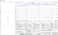
Example how one could estimate slot issues with "ideal transducer" in VituixCAD diffraction tool.
You'd be sure the baffle would make diffraction like any up until "the slot" beams, which depends on its size. In reality, the slot would have more chaotic response around the slot size wavelengths, and above, but you shouldn't use it that high anyway. It would also have acoustic low pass, perhaps response is already dropping there.
Example: Big baffle with "slot", where the baffle is roughly 340Hz in size (wavelength about 1m), the slot is roughly 3.4kHz (wavelength about 10cm) in size in horizontal dimension. Response is bad from baffle size up, because the slot makes wide radiation that reaches the edge, where diffraction backwave emits and making interference with direct sound seen as undulation in the response. Above slot size frequencies the slot beams and no interference seen anymore, but here response to any direction would be chaotic most likely, also dropping response due to acoustic low pass. Look the polar plot to see how much such sized sound source would beam in ideal case, while real life it likely has even more undulation to various directions, more than here. Slot isn't likely usable beyond this due to beaming / "chaos", and due to acoustic low pass. "best" usable bandwidth here is below baffle size, like always with any sound source on any baffle, because there is less and less secondary sound emitted at the edge. Roundovers would help of course.
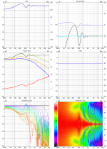
Example 2: if slot is no bigger than baffle, the usable bandwidth is now from slot size down. I'm kinda abstracting the slot away here to show it would be roughly similar in system performance terms as similar sized sound source, except likely bit worse. So, best slot is no slot. Slot has benefits too, the acoustic low pass would low pass distortion as well. So, wanna use slot, make it small and factor the cavity so that the acoustic low pass helps you out.
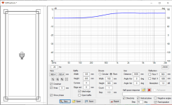
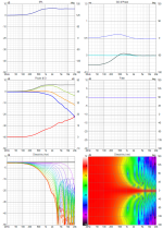
Above is how to "simplify" and just reason with wavelength to physical object size and how they interact, to get intuition and ballpark idea just by thinking it through. Real world graphs would always be worse than simplified simulation with ideal transducer. This example does not show any driver related things like cone resonances, or resonances in the cavity between driver and baffle and so on. Most of these would happen above driver size frequencies. Real world sound could be just fine though beyond what I idealize here, to some extent, which are things determined by you, what you are looking for, what is important and what is not. If there is a slot, it's there probably with some reason with associated trade-offs. If trade-offs outweight benefits it would be better to change the plan.
Hope it helps, have fun with imagination!
You'd be sure the baffle would make diffraction like any up until "the slot" beams, which depends on its size. In reality, the slot would have more chaotic response around the slot size wavelengths, and above, but you shouldn't use it that high anyway. It would also have acoustic low pass, perhaps response is already dropping there.
Example: Big baffle with "slot", where the baffle is roughly 340Hz in size (wavelength about 1m), the slot is roughly 3.4kHz (wavelength about 10cm) in size in horizontal dimension. Response is bad from baffle size up, because the slot makes wide radiation that reaches the edge, where diffraction backwave emits and making interference with direct sound seen as undulation in the response. Above slot size frequencies the slot beams and no interference seen anymore, but here response to any direction would be chaotic most likely, also dropping response due to acoustic low pass. Look the polar plot to see how much such sized sound source would beam in ideal case, while real life it likely has even more undulation to various directions, more than here. Slot isn't likely usable beyond this due to beaming / "chaos", and due to acoustic low pass. "best" usable bandwidth here is below baffle size, like always with any sound source on any baffle, because there is less and less secondary sound emitted at the edge. Roundovers would help of course.


Example 2: if slot is no bigger than baffle, the usable bandwidth is now from slot size down. I'm kinda abstracting the slot away here to show it would be roughly similar in system performance terms as similar sized sound source, except likely bit worse. So, best slot is no slot. Slot has benefits too, the acoustic low pass would low pass distortion as well. So, wanna use slot, make it small and factor the cavity so that the acoustic low pass helps you out.


Above is how to "simplify" and just reason with wavelength to physical object size and how they interact, to get intuition and ballpark idea just by thinking it through. Real world graphs would always be worse than simplified simulation with ideal transducer. This example does not show any driver related things like cone resonances, or resonances in the cavity between driver and baffle and so on. Most of these would happen above driver size frequencies. Real world sound could be just fine though beyond what I idealize here, to some extent, which are things determined by you, what you are looking for, what is important and what is not. If there is a slot, it's there probably with some reason with associated trade-offs. If trade-offs outweight benefits it would be better to change the plan.
Hope it helps, have fun with imagination!
Last edited:
Very interesting. Lets say one wants to use a diffraction slot on a 12 inch speaker to better match a small horn (or "K-tube") mounted on top of a cabinet. How might they pick in advance a best slot shape? - or should the exercise be carried out empirically with cardboard lenses and measurements ? (could be faster).
In the 1960's John Karlson devised and marketed a line of "asymmetric projectors" claiming wide coverage of rectangular areas (-nearly 20 year before Don Keele Jr.). I know these "worked" or seemed to in a sense. They were mounted high at a wall and if one sat pretty close to that wall and around floor level they sounded reasonably clear.
What does the tapered slot in Karlson's "clam/klam" really do with regards to dispersion patterns? The front chamber is relatively deeper than Karlson's Ultra Fidelity stuff and can cause more problems (probably when small)
How do you view the regular Karlson enclosures? I would ditch them but with good driver match they sound "more real" with drums than any of my limited FLH collection. I've also heard horrid stuff from them with some drivers.
Attachments
- Home
- Loudspeakers
- Multi-Way
- Studies or papers on slot loaded woofer directivity?
