
Can anyone tell me if Krell output transistors - part #'s 484081 and 484002 from a KSA-300s could be used for my KSA 100 build. I have access to quite a few of these, but I am having trouble cross referencing the unique Krell part numbers.
You can get the originals free from ON-Semi, you pay shipping, so not totally free.
The board is from JIM:
High Power Pure Class A Amplifier PCB KSA50 MKII | eBay
If you go to:
Semiconductor and Integrated Circuit Devices
search for MJ15003/MJ15004 and request samples, I think you're allowed 5 free, you'll get enough for a ksa50, you'll need to pay to get more..easy
I know you previously mentioned you're building a ksa100, the board above is for the 50. I also have that red board, as I originally planned to build the 100 as well. The board above is slightly different in that the red version has mosfet pre-drivers. The ksa50 I built above puts alot of heat out, and it certainly does not 'sound' like a 50 watt amp.....sounds phenomenal!
Last edited:
I need some advice on heat sinks.
I am thinking of buying 2 of the chassis’s below. My build will be a pair of mono block KSA100’s and I'd like some feedback from others who have built this amp using passive cooling. I was thinking of mounting 4 outputs evenly spaced per heat sink on an aluminum L-channel.
I am estimating that the heat sinks are 13” x 7” with 1” fins.
KSA 50s Big Class A Amplifier Full Aluminum Chassis Case Enclosure 480 224 424mm | eBay
Hi Ralph, I am sure you have done the math regarding heat sinking, here are my thoughts:
One channel: for 100WRMS into 8 Ohms-
4 pairs of output devices
48V rails
1 Ohm emitter resistors
630mV across each resistor
This gives 100 W RMS into 8 Ohms
242W heat dissipation.
For your mono bloc that would mean approx 120W per side. I think that the size of the heat sinks on the chassis you mentioned are much too small.
The de-rated KSA 50 ( KSA25 ) that I built dissipates about 65W per side with heat sinks that measure 400mm X 130mm X 40mm , it runs at approx 30C above ambient.
Only my thoughts gained from experience and mistakes.
Hope it helps
Alan

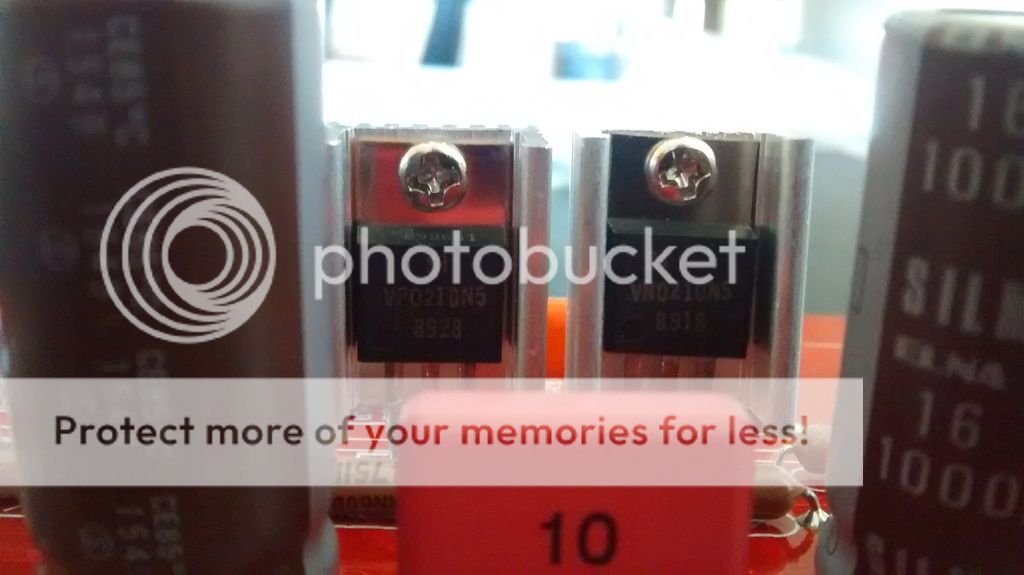
Christmas in July!
Lots of parts have arrived this week, so far I have most of the driver boards soldered, just waiting for some heat sinks to complete.
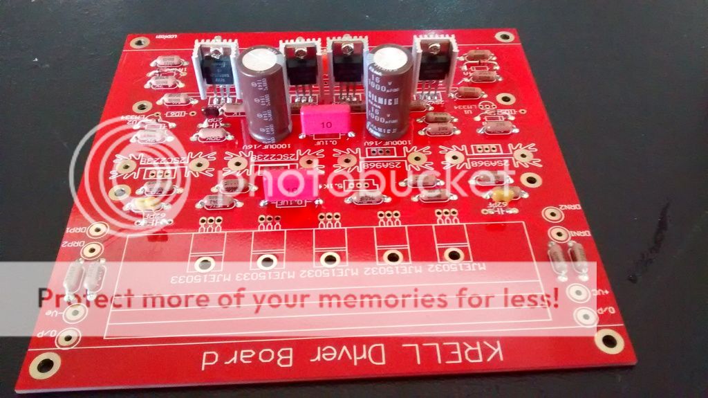
I was lucky and was able to source some VP0210N and VN0210N! I am using individual heat sinks on the VP's and VN's, I think these should do the job, together they have a bit more surface area that the aluminum bar which Krell used and I don't need to worry able electrical isolation. Fingers crossed!!
I wasn't able to source from legitimate suppliers any 2SA968 OR 2SC2238 ( I do have quite a few I've purchased from Ebay - but I have yet to determine if they are real or fakes). So I am going to substitute these with 2SC2336 and 2SA1006 that I purchased from a good source. Any thoughts?
Lots of parts have arrived this week, so far I have most of the driver boards soldered, just waiting for some heat sinks to complete.

I was lucky and was able to source some VP0210N and VN0210N! I am using individual heat sinks on the VP's and VN's, I think these should do the job, together they have a bit more surface area that the aluminum bar which Krell used and I don't need to worry able electrical isolation. Fingers crossed!!

I wasn't able to source from legitimate suppliers any 2SA968 OR 2SC2238 ( I do have quite a few I've purchased from Ebay - but I have yet to determine if they are real or fakes). So I am going to substitute these with 2SC2336 and 2SA1006 that I purchased from a good source. Any thoughts?
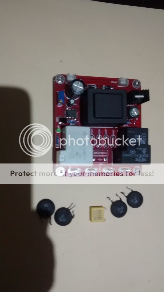
I purchased these soft start units with over-temperature shut-off on Ebay and did a few mods. I don't think the relays contacts would survive long term with the current draw of the KSA100, so I decided to remove the NTC's and use the relays to drive the coils on 2 contactors, the first contactor will have a 5R/50W power resistor for current limiting and the second contactor will send power direct. I've chosen 120V coil/40amp contactors. Hopefully this combination should provide long service life.
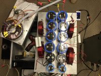
Also had a chance to remove, test and re-solder 72 capacitors on my capacitor boards,(1 for each channel), these are original Krell boards, don't know what 2 channel amp they were used in, but I got a deal on 6 because each board has a few bad caps.
36 - 3300mfd/100V caps and ground plane for all my ground connections. I think these should work well.
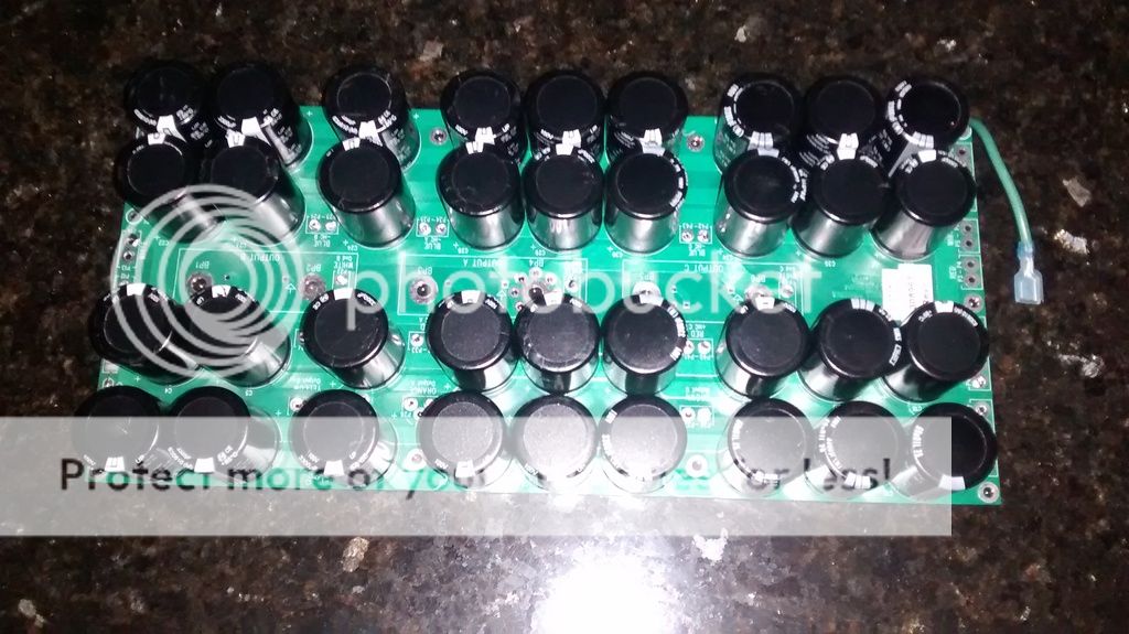
There are 2 - 10K resistors paralleled to the capacitors, I don't know whether to reuse these or remove them.
")
View attachment 557837
The fan only cools about 11c from the internal fin area, but its just enough to make a difference
Where did you get those beautiful chassis from?
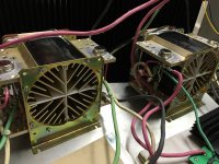
My chassis' finally arrived and I've started assembly.
Fans, softstart and contactors installed. Under the softstart is a 12v power supply for the fans,
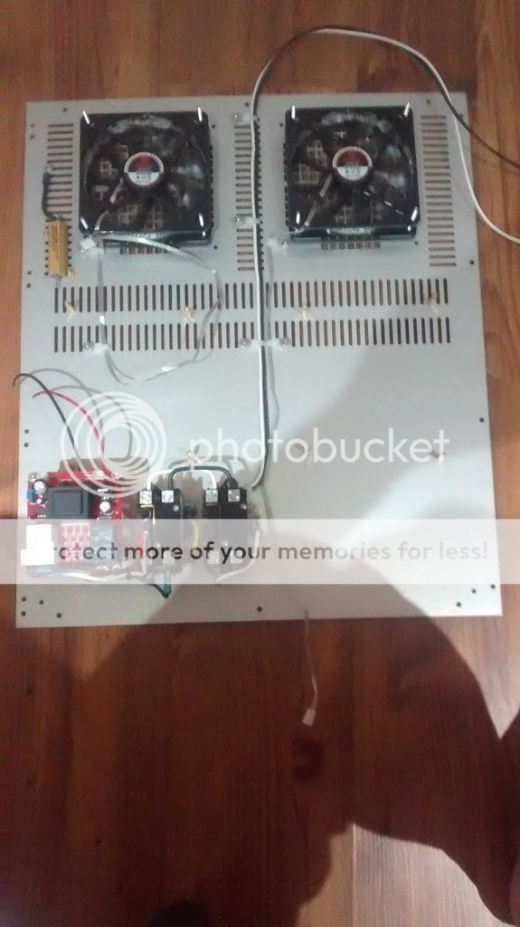
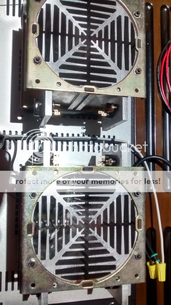
Trial fitting the heatsinks.
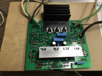
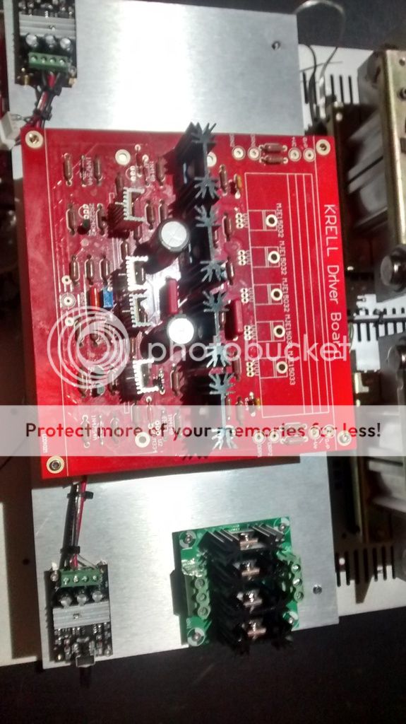
Two fan speed controllers, rectifier board and trial fit driver board. The capacitor bank is below this.
I'm hoping to have the first amp wired over the weekend!
Fans, softstart and contactors installed. Under the softstart is a 12v power supply for the fans,

Trial fitting the heatsinks.

Two fan speed controllers, rectifier board and trial fit driver board. The capacitor bank is below this.

I'm hoping to have the first amp wired over the weekend!


- Status
- This old topic is closed. If you want to reopen this topic, contact a moderator using the "Report Post" button.
- Home
- Amplifiers
- Solid State
- Stolen Trademark Amplifier from Jim's Audio on EBAY