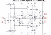
Hi all, thanks Spurite for the great information. Have you a circuit diagram of Jim's boards that you can post so that I can start getting components up together.
Thanks for your help
Alan.
You should have them, if you bought the boards from him.
Attachments
Sorry Alibear. I thought you wanted something more than what MEGA-amp shows you what Jim's Audio provides either by email or through ebay messages. I reread my quote and it sounds I was a bit of an *** ****. I was on the train trying to find what Jim's Audio had to sent me to send to you on my cell phone. Sorry again.
Still Workin'
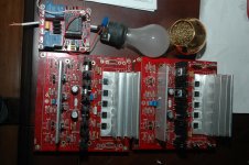
I got some nylon screws and nuts, drilled out holes in these heatsinks, and had to resolder some of the trannies. Lifes a bitch the you die. What I mean, I don't like moving solder or its heat. This is what I mean when I say Jim's Audio's board are good ****. They take a beating and still ticking.
I got some nylon screws and nuts, drilled out holes in these heatsinks, and had to resolder some of the trannies. Lifes a bitch the you die. What I mean, I don't like moving solder or its heat. This is what I mean when I say Jim's Audio's board are good ****. They take a beating and still ticking.
Attachments
schematic
Neychi, do you have the speaker protection's schematic? I seem to have misplaced mine. I have the same speaker protection.David, I want to have all the heatsinks in the same color. That's why I will give them to the black anodizing.
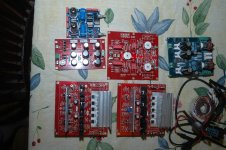
More progress...
If you trace out just what the signal goes with speaker protection, I,m sure it get polluted along the way. No thanx
I have never needed one as long as you spend time on the bench with different extreme loasds and get a feel for what works.
I have built 6 monoblock Krells with no issue and even use the delicate Quad electrostatics with no harm. Sometimes your amp gives a warning as did my 150's once with PS caps starting to go, but I missed some smoke by being fast with the mute
Now if I was a Manufacturer giving a loaded gun to a customer with a drinking problem, then this would be reason enough to have it on an amp to keep the dealer/customer relation warm and happy!
Best sound quality and living on the edge gives the best combination of enjoyment IMO
Test pilot Chuck Yeager Would be bored any other way!
Regards
David
Neychi, do you have the speaker protection's schematic? I seem to have misplaced mine. I have the same speaker protection.
Here it is
")
Attachments
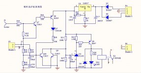
speaker protection.
I have a while yet to get to that point. Lots of summer activities, but I fully understand. Will try both ways and trace for noise. Thanks AVWERK very much.I should have said to pull the speaker wires.
If you do build the speaker protection, make it in such a way to be able to disconnect to try both ways and see if you can hear a difference
I should have said to pull the speaker wires.
If you do build the speaker protection, make it in such a way to be able to disconnect to try both ways and see if you can hear a difference
In my opinion that is a silly statement. You may as well solder the speaker terminals directly to the amp output transistors to hear (not see) if there is a difference between having speaker connectors and wire or not.

Kaplaars - Your build has given me new inspiration to tackle a BIG amp project. The Krell clone looks more and more like the one I will select. Your workmanship is nothing short of beautiful - truly a work of tecno-modern art! You should be very proud. I haven't read the entire thread yet, but is yours completed and functional yet?
Do you have any idea what the equivalent (in US $) it has cost you to build? Just curious about that little fact, should I decide to adventure into the next level of DIY'ing. Great job!
Rick
Do you have any idea what the equivalent (in US $) it has cost you to build? Just curious about that little fact, should I decide to adventure into the next level of DIY'ing.
Great job!Rick
Hi Andrew,
Why is it a bad idea for NTC's to be mounted in parallel?
I know the mains capacitor has to be X or Y rated. Like I posted earlier the capacitor that is in series with the mains is x1, y2 rated. But that is not really my question. I dont understand why this capacitor is placed in series with the mains. I also do not entirely understand what is wrong with the C's parallel to the bridge. Can you explain that to me?
as soon as current flows thru the NTC, it heats up and from a cold resistance of about 4 to 8 ohms, the hot resistance drops much below 1 ohm...
it is never a good idea to parallel NTC's since the resulting equivalent resistance will be low such that you defeat the purpose for which you wanted to install that in the first place...limit the inrush current...the higher the resistance you put in series with your power traffo the lower the starting current...
finally, imho shorting out the NTC with relay contacts is really not necessary...
Check out this liquid cooled setup from this F5 thread http://www.diyaudio.com/forums/pass-labs/236621-starting-build-my-first-f5-turbo-v3-7.html
Kaplaars - Your build has given me new inspiration to tackle a BIG amp project. The Krell clone looks more and more like the one I will select. Your workmanship is nothing short of beautiful - truly a work of tecno-modern art! You should be very proud. I haven't read the entire thread yet, but is yours completed and functional yet?
Do you have any idea what the equivalent (in US $) it has cost you to build? Just curious about that little fact, should I decide to adventure into the next level of DIY'ing.
Rick
Hi Rick,
Sorry for my late reply to your post. I have been very busy lately. My grandparents just moved out to an seniors apartment. And offcourse being the only semi-electrician in the family, they needed me to wire a few new power joints for their kitchen... yes the KSA project needed to wait again
Thank you
! I am pleased to hear that you like the amp. I putted a lot of effort into it, but I am not statisfied yet Mine was complete and functional. But my thermal design turned out to be not as efficient as I had hoped for. So I took the radical decision to change it completely. I think the amp will be far more better to cope with the large amount of heat it will generate compared to the previous setting. Thermal management is very important. Especially when you would like to go full bias. I am not fully aware of US prices for parts. But here in Holland there are few flea markets a year were I can buy parts relatively cheap. You can save a lot of money when buying parts second handed. Via eBay for example. The transformers, tunnel coolers and cabinet will take probably the lion share of your costs. I have spent just about 550 dollars right now, and unfortunatelly the meter is still counting. You can make the amp as expensive as you wish (gold plated cables and that kind of money eating additions
). But from the other hand, I stongly believe it is possible to build an amplifier like this one for less money. 400 dollars should be doable. But in that case you seriously need to cut into costs of details, like the custom made rear panel I made etc. I know 550 dollars is a lot of money, but I have to say Rick, it has been worth every dollar thusfar. It is not an easy project. It takes a lot of your time, but believe me when I say, it truly gives a lot of statisfaction, it is something you have made, and there is not an other one around I will post some new photo's soon. Yes I have not been sitting down all the time
. But first I need to clean my desk, since this beast had just been repaired and restored and also takes a lot of space (very underestimated amplifier):An externally hosted image should be here but it was not working when we last tested it.
.JPG)
An externally hosted image should be here but it was not working when we last tested it.
Hi Friends,
As promised, another update from my hand In the previous posts I attached some pictures of the backplate wich the driver boards are attached to. I've red on the internet about fan shrouds. A schroud is a piece of hollow material between the fan and the air intake to distribute the air more uniform. At the bottom of my cabinet there are some predrilled ventilation holes. So I decided to make two 'air chambers' which function as a shroud and form a bridge between the ventilation holes at the bottom and the tunnel coolers. Another benefit in this configuration is that I can utilize all the ventilation holes (because the fram spans the whole area), which results in more airflow, and I dont have to cut ugly holes. Because the KSA-100 is getting heavy I also wanted to reinforce the cabinet a bit more. So I decided to fabricate the airchaimbers from hollow iron square profiles which I miter sawed. Together it adds up to a very strong frame:
Next it was time to attach the tunnel coolers. I bought a relatively thick aluminium sheet (0,15 inch), so it can cope easy with the large amounth of weight of the tunnel coolers, which will rest on top of this sheet. I bought a fretsaw to cut the ventilation holes. Something that was nog easy, those saw blades snap very fast. Let alone the thickness of the aluminium. But I don't give up that fast and after a few hours I got two nice ventilation holes. I started with drawing the intake using a square resulting into an octagon. Next I drilled carefully a little hole into every corner of the figure:
Next it was time to attach the aluminum sheet to the aluminum frame I have made earlier. Resulting in:
As you can see, I made the aluminum sheet a bit larger than the frame. This is deliberately, the sheet will span from the frame to the rear plate. So I can hide cables underneath this plate. I am very glad how this little experiment turned out. It really works! And it is rock solid. The tunnel coolers are connected directly to the chassis and thus to ground. This way the tunnels are no longer 'live' and the aluminium sheet offers even more cooling capacity, because the tunnel coolers are thermally coupled to the sheet and the aluminum frame below. Also this way the tunnel coolers can exchange heat with each other (probably not that good, but every bit helps) better than in my previous configuration. So thermal runaway of one channel should be more difficult to occur. Now it is time to mount the unit into the cabinet. But before that I need to wire the TO-3's. I am still doubting about making an PCB to mount the TO-3's to. I also have to add thermal protection (clicsons), sensors and I am thinking of rearranging the rear panel (maybe I put the speaker protection somewhere else into the cabinet), and I want to make a new fuse box. Anddd... I will polish the metal a bit . So a lot of work to do. Glad there is no hurry
As promised, another update from my hand
In the previous posts I attached some pictures of the backplate wich the driver boards are attached to. I've red on the internet about fan shrouds. A schroud is a piece of hollow material between the fan and the air intake to distribute the air more uniform. At the bottom of my cabinet there are some predrilled ventilation holes. So I decided to make two 'air chambers' which function as a shroud and form a bridge between the ventilation holes at the bottom and the tunnel coolers. Another benefit in this configuration is that I can utilize all the ventilation holes (because the fram spans the whole area), which results in more airflow, and I dont have to cut ugly holes. Because the KSA-100 is getting heavy I also wanted to reinforce the cabinet a bit more. So I decided to fabricate the airchaimbers from hollow iron square profiles which I miter sawed. Together it adds up to a very strong frame: An externally hosted image should be here but it was not working when we last tested it.
.JPG)
An externally hosted image should be here but it was not working when we last tested it.
.JPG)
Next it was time to attach the tunnel coolers. I bought a relatively thick aluminium sheet (0,15 inch), so it can cope easy with the large amounth of weight of the tunnel coolers, which will rest on top of this sheet. I bought a fretsaw to cut the ventilation holes. Something that was nog easy, those saw blades snap very fast. Let alone the thickness of the aluminium. But I don't give up that fast and after a few hours I got two nice ventilation holes. I started with drawing the intake using a square resulting into an octagon. Next I drilled carefully a little hole into every corner of the figure:
An externally hosted image should be here but it was not working when we last tested it.
.JPG)
An externally hosted image should be here but it was not working when we last tested it.
.JPG)
An externally hosted image should be here but it was not working when we last tested it.
.JPG)
An externally hosted image should be here but it was not working when we last tested it.
.JPG)
Next it was time to attach the aluminum sheet to the aluminum frame I have made earlier. Resulting in:
An externally hosted image should be here but it was not working when we last tested it.
.JPG)
An externally hosted image should be here but it was not working when we last tested it.
.JPG)
An externally hosted image should be here but it was not working when we last tested it.
.JPG)
An externally hosted image should be here but it was not working when we last tested it.
.JPG)
As you can see, I made the aluminum sheet a bit larger than the frame. This is deliberately, the sheet will span from the frame to the rear plate. So I can hide cables underneath this plate
. I am very glad how this little experiment turned out. It really works! And it is rock solid. The tunnel coolers are connected directly to the chassis and thus to ground. This way the tunnels are no longer 'live' and the aluminium sheet offers even more cooling capacity, because the tunnel coolers are thermally coupled to the sheet and the aluminum frame below. Also this way the tunnel coolers can exchange heat with each other (probably not that good, but every bit helps) better than in my previous configuration. So thermal runaway of one channel should be more difficult to occur. Now it is time to mount the unit into the cabinet. But before that I need to wire the TO-3's. I am still doubting about making an PCB to mount the TO-3's to. I also have to add thermal protection (clicsons), sensors and I am thinking of rearranging the rear panel (maybe I put the speaker protection somewhere else into the cabinet), and I want to make a new fuse box. Anddd... I will polish the metal a bit . So a lot of work to do. Glad there is no hurry
Last edited:
- Status
- This old topic is closed. If you want to reopen this topic, contact a moderator using the "Report Post" button.
- Home
- Amplifiers
- Solid State
- Stolen Trademark Amplifier from Jim's Audio on EBAY