Heat Sinks
The dimensions are 19cm by 16cm while the fins are 7cm, not including 5 1/2 cm mounting bank.Yes, I am going to use two fans for push/pull effects.
An externally hosted image should be here but it was not working when we last tested it.
May I ask what are your output trannies and did you make your own PCBs for them?
May I ask what are your output trannies and did you make your own PCBs for them?
Yes ı did my own output PCB s because first I made orjinal output pcb and I used MJ15004 and MJ15003 but when I measured bias they are very difrent value for example MJ15004 is 575 mv MJ15003 is 475 mv . 100 mv difrence so i didin't like it . perhaps they are bulk. So I tested MJL21193 and MJL21194 their difrences bias is 10-15 mv . Then I made my pbc for them.
Can I ask you? I mesaured bias between MJL21194's emitter and base is it true points ? İf isn't true where is the true point ? Can you expleain clearly
An externally hosted image should be here but it was not working when we last tested it.
@ what current (Ic)?...........MJ15003 but when I measured bias they are very difrent value for example MJ15004 is 575 mv MJ15003 is 475 mv . 100 mv difrence so i didin't like it..........
@ what voltage (Vce)?
@ what temperature (Tj, or Tc)?
PCB circuit correction for MJ15s
Just wondering if you observed the correct Kaplaars made for the MJE15s circuits. Please look at page 15 #141 for pictures for the jumper needed. Thanks Kaplaars for finding this error.Yes ı did my own output PCB s because first I made orjinal output pcb and I used MJ15004 and MJ15003 but when I measured bias they are very difrent value for example MJ15004 is 575 mv MJ15003 is 475 mv . 100 mv difrence so i didin't like it . perhaps they are bulk. So I tested MJL21193 and MJL21194 their difrences bias is 10-15 mv . Then I made my pbc for them.
Can I ask you? I mesaured bias between MJL21194's emitter and base is it true points ? İf isn't true where is the true point ? Can you expleain clearly
An externally hosted image should be here but it was not working when we last tested it.
Hi Kaplaars,
I bought the same "Class A power delay soft-start temperature protection board 110V/220V | eBay". Could you let me know which capacitors you replaced to eliminate the bouncing issue?
Thanks,
cfy30
I bought the same "Class A power delay soft-start temperature protection board 110V/220V | eBay". Could you let me know which capacitors you replaced to eliminate the bouncing issue?
Thanks,
cfy30
Hi cfy30,
I had the same soft start ordered and also made changes, but everytime the main fuse blows out.
The seller has sent me 2 sofstarts for free and those works perfect.
http://www.ebay.com/itm/Assembled-H..._Components&hash=item1c1e8c0a2d#ht_832wt_1091
Regards,
Rudy
I had the same soft start ordered and also made changes, but everytime the main fuse blows out.
The seller has sent me 2 sofstarts for free and those works perfect.
http://www.ebay.com/itm/Assembled-H..._Components&hash=item1c1e8c0a2d#ht_832wt_1091
Regards,
Rudy
Attachments
Last edited:
cool stuff shared on heat sinks on John Curl's preamp thread: http://www.diyaudio.com/forums/anal...urls-blowtorch-preamplifier-part-ii-3778.html
@Fix; Cool to see you here, I would love to see another build from your hand!!! ") You were a big inspiratory to me for building a KSA myself. When I saw your build journals in the other KSA thread, I thought immediately ‘I WANT ONE TOO’ . By the way fix, how much difference made it for temperature when you cutted the bottom panel open for the tunnel coolers? I have the same cabinet as your, but I use slightely larger cooling tunnels. I am still thinking about making holes for the new tunnel coolers in the bottom plate too, or just using the holes that are already in the bottom plate to gain fresh air. It will be not a problem to cut the bottom plate open, but I am afraid the cabinet will be less rigid. Probably have to make reinforcements then, or will this be not a big problem?
You were a big inspiratory to me for building a KSA myself. When I saw your build journals in the other KSA thread, I thought immediately ‘I WANT ONE TOO’ . By the way fix, how much difference made it for temperature when you cutted the bottom panel open for the tunnel coolers? I have the same cabinet as your, but I use slightely larger cooling tunnels. I am still thinking about making holes for the new tunnel coolers in the bottom plate too, or just using the holes that are already in the bottom plate to gain fresh air. It will be not a problem to cut the bottom plate open, but I am afraid the cabinet will be less rigid. Probably have to make reinforcements then, or will this be not a big problem?
@cfy30; Particular those little 2uF caps were up to no good (bad quality). You need to replace these caps with MKT’s or something similar. I’ve replaced them with 1uF caps instead of the original 2uF ones. I think the relays bounce initially because the transformers alone (with no load attached to them) are almost equivalent to an inductive load. Something relays in general do not like. For example, when I tested the softstart with a more resistive-like load (a big light bulb), I did not experience any bouncing of the relays. Further this circuit is very sensitive when it comes to contacting of the switch with the original caps. When the switch made contact a bit too long, it shuts inmediately down after starting. If the relay keeps bouncing there is a good possibility your fuses will blow. This can happen because the NTC’s are already warm. So when it keeps starting up and shutting down, the inrush current will not be dampened by the NTC’s. Resulting in tripping the RCD or blow the fuses. With replacing the little 2uF caps I have never experienced these problems again, even when switching rather inductive loads. To be sure I've replaced all caps on the little PCB.
I’ve seen some nice builds coming by! Good that this tread stays vivid! And complements to the eager builders!!!
I’ve made a little bit of progress myself too.
Now I know my sawguide works perfectly I can cut iron much easier, and more important, without non-straight cuts. I've started with cutting a new backplate for the boards and made the heatsinks for the MJE150033/32 a little bit shorter.
Further I've decided to move the soft start to the front side of my amplifier instead of the rear side. I have had no hum at all, but the soft start was in my opinion still a little too close to the speaker terminals when reconsidering my first lay-out. So I had to make a little plate to mount the soft start PCB to.
It is slowly coming together again. I am still thinking about making new PCB's to mount the TO-3's at since the original PCB's do not fit to the holes in my pre fab new heat sink. And offcourse I don't want to ruin them with drilling in them like there is no tommorow Another option is to hardwire the TO-3's. I've got nice mounting sockets. I am not sure what will be the best solution. Still have to think about that.
My new lay out will be very similair to this:
But I am still fine tuning. Also I've invested in new cooling equipment. At the heatsinks are two 14cm fan shrouds attached. Two 14cm fans will be attached on top of them. Lots of airflow, and more important, less noise. The heatsinks themself are not attached to the cabinet yet, so there still is some room to play and to find the optimal layout.
Another point of consideration are the holes in the side panels. Both side panels now have an ugly 9.2cm hole which they have herited from my the first configuration. I am thinking of mounting two iron 12cm papst fans at each side so the panels stay very strong (because of the iron housing of the papst fans) and offer even more airflow. Offcourse, than I will have to cut a new, slightely larger gap + mount new fan grilles. But that will not be a big problem. The plate which the driving boards are attached to offers in this configuration a very nice air duct to guide the air in and out, without dispersing through the cabinet, but going in and out directly. Have to see if this will help to keep temperature down even more. If not I just have buy two new side pannels Luckaly these panels are not that expensive, but still...
Busy times over here. So further progress is made rather slowly, but will post some pictures when there are new updates
Edit: typo
You were a big inspiratory to me for building a KSA myself. When I saw your build journals in the other KSA thread, I thought immediately ‘I WANT ONE TOO’ . By the way fix, how much difference made it for temperature when you cutted the bottom panel open for the tunnel coolers? I have the same cabinet as your, but I use slightely larger cooling tunnels. I am still thinking about making holes for the new tunnel coolers in the bottom plate too, or just using the holes that are already in the bottom plate to gain fresh air. It will be not a problem to cut the bottom plate open, but I am afraid the cabinet will be less rigid. Probably have to make reinforcements then, or will this be not a big problem? @cfy30; Particular those little 2uF caps were up to no good (bad quality). You need to replace these caps with MKT’s or something similar. I’ve replaced them with 1uF caps instead of the original 2uF ones. I think the relays bounce initially because the transformers alone (with no load attached to them) are almost equivalent to an inductive load. Something relays in general do not like. For example, when I tested the softstart with a more resistive-like load (a big light bulb), I did not experience any bouncing of the relays. Further this circuit is very sensitive when it comes to contacting of the switch with the original caps. When the switch made contact a bit too long, it shuts inmediately down after starting. If the relay keeps bouncing there is a good possibility your fuses will blow. This can happen because the NTC’s are already warm. So when it keeps starting up and shutting down, the inrush current will not be dampened by the NTC’s. Resulting in tripping the RCD or blow the fuses. With replacing the little 2uF caps I have never experienced these problems again, even when switching rather inductive loads. To be sure I've replaced all caps on the little PCB.
I’ve seen some nice builds coming by! Good that this tread stays vivid!
And complements to the eager builders!!!I’ve made a little bit of progress myself too
.Now I know my sawguide works perfectly I can cut iron much easier, and more important, without non-straight cuts. I've started with cutting a new backplate for the boards and made the heatsinks for the MJE150033/32 a little bit shorter.
An externally hosted image should be here but it was not working when we last tested it.
An externally hosted image should be here but it was not working when we last tested it.
Further I've decided to move the soft start to the front side of my amplifier instead of the rear side. I have had no hum at all, but the soft start was in my opinion still a little too close to the speaker terminals when reconsidering my first lay-out. So I had to make a little plate to mount the soft start PCB to.
An externally hosted image should be here but it was not working when we last tested it.
An externally hosted image should be here but it was not working when we last tested it.
It is slowly coming together again. I am still thinking about making new PCB's to mount the TO-3's at since the original PCB's do not fit to the holes in my pre fab new heat sink. And offcourse I don't want to ruin them with drilling in them like there is no tommorow
Another option is to hardwire the TO-3's. I've got nice mounting sockets. I am not sure what will be the best solution. Still have to think about that.My new lay out will be very similair to this:
An externally hosted image should be here but it was not working when we last tested it.
An externally hosted image should be here but it was not working when we last tested it.
But I am still fine tuning. Also I've invested in new cooling equipment. At the heatsinks are two 14cm fan shrouds attached. Two 14cm fans will be attached on top of them. Lots of airflow, and more important, less noise. The heatsinks themself are not attached to the cabinet yet, so there still is some room to play and to find the optimal layout.
Another point of consideration are the holes in the side panels. Both side panels now have an ugly 9.2cm hole which they have herited from my the first configuration. I am thinking of mounting two iron 12cm papst fans at each side so the panels stay very strong (because of the iron housing of the papst fans) and offer even more airflow. Offcourse, than I will have to cut a new, slightely larger gap + mount new fan grilles. But that will not be a big problem. The plate which the driving boards are attached to offers in this configuration a very nice air duct to guide the air in and out, without dispersing through the cabinet, but going in and out directly. Have to see if this will help to keep temperature down even more. If not I just have buy two new side pannels
Luckaly these panels are not that expensive, but still...Busy times over here. So further progress is made rather slowly, but will post some pictures when there are new updates
Edit: typo
Last edited:
2uF capacitors/softstart
This is funny and maybe you can help. I have the same softstarts as Kaplaars. Yes two, as I am thinking of building two mono blocks. The little softstart PCBs are printed as 2uF but 22uFs are soldered in its place. What gives? Will it still be advisable to replace the 22uFs with 1uFs?@Fix; Cool to see you here, I would love to see another build from your hand!!!
@cfy30; Particular those little 2uF caps were up to no good (bad quality). You need to replace these caps with MKT’s or something similar. I’ve replaced them with 1uF caps instead of the original 2uF ones. I think the relays bounce initially because the transformers alone (with no load attached to them) are almost equivalent to an inductive load. Something relays in general do not like. For example, when I tested the softstart with a more resistive-like load (a big light bulb), I did not experience any bouncing of the relays. Further this circuit is very sensitive when it comes to contacting of the switch with the original caps. When the switch made contact a bit too long, it shuts inmediately down after starting. If the relay keeps bouncing there is a good possibility your fuses will blow. This can happen because the NTC’s are already warm. So when it keeps starting up and shutting down, the inrush current will not be dampened by the NTC’s. Resulting in tripping the RCD or blow the fuses. With replacing the little 2uF caps I have never experienced these problems again, even when switching rather inductive loads. To be sure I've replaced all caps on the little PCB.
I’ve seen some nice builds coming by! Good that this tread stays vivid!
I’ve made a little bit of progress myself too
Now I know my sawguide works perfectly I can cut iron much easier, and more important, without non-straight cuts. I've started with cutting a new backplate for the boards and made the heatsinks for the MJE150033/32 a little bit shorter.
.JPG)
.JPG)
Further I've decided to move the soft start to the front side of my amplifier instead of the rear side. I have had no hum at all, but the soft start was in my opinion still a little too close to the speaker terminals when reconsidering my first lay-out. So I had to make a little plate to mount the soft start PCB to.
.JPG)
.JPG)
It is slowly coming together again. I am still thinking about making new PCB's to mount the TO-3's at since the original PCB's do not fit to the holes in my pre fab new heat sink. And offcourse I don't want to ruin them with drilling in them like there is no tommorow
My new lay out will be very similair to this:
.JPG)
.JPG)
But I am still fine tuning. Also I've invested in new cooling equipment. At the heatsinks are two 14cm fan shrouds attached. Two 14cm fans will be attached on top of them. Lots of airflow, and more important, less noise. The heatsinks themself are not attached to the cabinet yet, so there still is some room to play and to find the optimal layout.
Another point of consideration are the holes in the side panels. Both side panels now have an ugly 9.2cm hole which they have herited from my the first configuration. I am thinking of mounting two iron 12cm papst fans at each side so the panels stay very strong (because of the iron housing of the papst fans) and offer even more airflow. Offcourse, than I will have to cut a new, slightely larger gap + mount new fan grilles. But that will not be a big problem. The plate which the driving boards are attached to offers in this configuration a very nice air duct to guide the air in and out, without dispersing through the cabinet, but going in and out directly. Have to see if this will help to keep temperature down even more. If not I just have buy two new side pannels
Busy times over here. So further progress is made rather slowly, but will post some pictures when there are new updates
Edit: typo
I have two too (one for spare) . Indeed funny because the one that is used currently in my KSA had a 2uF MKT attached, but the other one had a normal 22uF capacitor soldered on this place. Probably they have had more problems, and tried to find a different solution. 22uF could work but probably only because a normal cap has higher ESR so switch bouncing is more dampened. I choose to lower capacity. I saw that similar like circuits using the same Ne555 are using an 1 uF capacitor too. That works for me. I have not tested the circuit with the 22uF capacitor. Have you experiented with it David? Do the relais bounce when you switch the transformers alone?
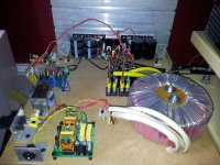
. Indeed funny because the one that is used currently in my KSA had a 2uF MKT attached, but the other one had a normal 22uF capacitor soldered on this place. Probably they have had more problems, and tried to find a different solution. 22uF could work but probably only because a normal cap has higher ESR so switch bouncing is more dampened. I choose to lower capacity. I saw that similar like circuits using the same Ne555 are using an 1 uF capacitor too. That works for me. I have not tested the circuit with the 22uF capacitor. Have you experiented with it David? Do the relais bounce when you switch the transformers alone?My Krell finished Only Krell logo will write on it. Kaplaars thank you for this forum. I want to make a new one again. They will be mono and mono. I have a meterials.
An externally hosted image should be here but it was not working when we last tested it.
An externally hosted image should be here but it was not working when we last tested it.

SoftStarts
I am fishing in Michigan on the Maumee River for walleye just south of Lake Erie. I will be home soon and I will experiment with soft start and transformer alone. Darn Kaplaars, you work fast. I will also test with a 100 watt light bulb before switching to 1uFs.I have two too (one for spare)
Yet it was easy. But you must cut front panel. I cut it with cnc machine and I bought
from ebay Vu Meter Driver Board Stereo with Backlite Voltage Output | eBay and 1pcs Classic Lake Blue Taiwan High Precision Vu Meter DB Level Meter | eBay
I will do left and right edge with woodwork for furniture perhaps center side to.
I have a problem. While all 47.000 mf condancer is emtpy I open the ksa 100 .The soft start role has spark. If 47.000 mf condancer is full stop and again start no spark.
I think it is a big problem. I used Class A Power Delay Soft Start Temperature Protection Board 110V 220V | eBay and 2 x 1000 va transformer.
Michael/Kaplaars
The latest layout looks excellent.
Consider putting the heat-tunnels on a base plate with opening at the bottom of the amp that will enable you to easily replace a fan without having to remove the whole heat-tunnel. With regular use fans do get noisy or need to be cleaned.
Regards
Jozua
The latest layout looks excellent.
Consider putting the heat-tunnels on a base plate with opening at the bottom of the amp that will enable you to easily replace a fan without having to remove the whole heat-tunnel. With regular use fans do get noisy or need to be cleaned.
Regards
Jozua
- Status
- This old topic is closed. If you want to reopen this topic, contact a moderator using the "Report Post" button.
- Home
- Amplifiers
- Solid State
- Stolen Trademark Amplifier from Jim's Audio on EBAY