Where is that data sheet for the 4055??
Its interesting, I started out replacing my brothers 4050II........
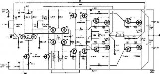
http://www.pitt.edu/~szekeres/sub/stk4050II.pdf
which has an older more distortive module. The II's were more expensive than the newer V's
from MCM Electronics, so that was an easy decision.
I wonder what the difference in makeup was, as i think the schematic is the same.
I had most of my diagrams from the Sanyo data cd disk I got from MCM. Any new ones I guess I'll have to check the sites. They seem to have a zillion old discontinued modules, and they all are not replacable.
Its interesting, I started out replacing my brothers 4050II........
http://www.pitt.edu/~szekeres/sub/stk4050II.pdf
which has an older more distortive module. The II's were more expensive than the newer V's
from MCM Electronics, so that was an easy decision.
I wonder what the difference in makeup was, as i think the schematic is the same.
I had most of my diagrams from the Sanyo data cd disk I got from MCM. Any new ones I guess I'll have to check the sites. They seem to have a zillion old discontinued modules, and they all are not replacable.
I don't know, but I got this idea to make sure the underside of my modules were flat. I got this machined piece of heatsink which I made sure was machined flat. I took the STK's and put some sandpaper under them between the flat heatsink.
They are not flat by any means. I was able to get
them pretty good, but once you get to a point, its diminishing returns. All in the name of heat tranference!
They are not flat by any means. I was able to get
them pretty good, but once you get to a point, its diminishing returns. All in the name of heat tranference!

So I see all these STK stuff as being deleted from the Sanyo line. What does the future hold?? I am interested in the switching amps. These are truley impressive. A 2 X 500 watt assembled block for $300 is not too bad if it works well. Anybody doing anything with these??
http://www.tripath.com/audio.htm
To All Interested Parties,
I've had several private emails over the last few months with various people regarding building STK amplifiers. I actually was attempting to build a couple more (in the old Tripath chassis's that had self-destructed; the power supplies were still good). However, I had two amps work fine and when testing a third amp, I had two STK modules flame-out the output resistors during testing when I switched from an 8 to a 4 ohm load. All amps were using the STK4048Xi. At least that's what I thought.
Initially, I wondered if I'd done something wrong. All parts were spot on correct. All modules were labelled STK4048XI. I spent several days going over all the STK issues. I had noticed one difference: there were different imprinted code numbers in the upper right corner on the plastic cover. But I had several and there was no rhyme. However, there seemed to be a pattern with thenumber on the rear of the devices. I ended up opening up several modules and finally resolved the matter. It required the use of several PDF datasheets that I had previously downloaded, covering almost all STK devices.
It turns out that not all STK4048XI are STK4048XI devices. That is, the outside label may say so, but the innards are totally different: different topology and different bipolar output devices. No wonder one set was stable and the other oscillated and flamed out
Anyhow, on the back of the devices, imprinted on the metal heat sinks are numbers. As near as I can figure out, those marked B404xxxx are garbage. Those marked with K404xxxx are great. My experience started with the B-series, and the weird results I was getting with feedback caps, etc (posted at the beginning of this thread) changed not because of any voodoo, but because I accidentally began using the K-series.
In studying the open devices, I found that the B-series is a quasi-complementary topology based on what was published as the STK4048II ('II' not the 'XI' version). The K-series is fully complementary and has the topology described in the 'XI' version datasheets.
The B-series uses SMT devices; the K-series, the unpotted guts of resistors and transistors. Fiddling with the K-series is almost impossible. Not so with the B-series. I located the critical SMT resistor controlling output bias and made one module stable. This work is not for the faint hearted, nor the tyro solderer. Simply opening the case can destroy circuit tracings, which are tricky to fix.
Nevertheless, since the B-series is quasi-complementary, I'm not interested in pursuing this task any further: I don't believe the sonics are worth the effort. Finding all this out did demonstrate that the oscillation and instability with low impedance loads was due to improperly adjusted bias. Unfortunately, the people who made the STK modules didn't externalize this resistor, so there is no easy fix.
The bottom line is that the manufacturer mislabeled units and therefore clouded the market with unreliable devices. I cannot but believe this has contributed to the various complaints I've read regarding STK amplifiers and their repair problems. The K-series should be fine to use as I've described using my uploaded PCBs. (If there are any other series imprints, I have no idea what they contain.)
Regards, Robert
ricen,
I've purchased pieces from several vendors and cannot be sure which can from where; my primary sources have been Mat electronics, Audio Lab of Georgia, and Techsonic.
I also had some STK4044XI with K404xxxx on the rear plate. These too were good units with true XI fully complementary circuitry. Again, this supports the idea that K-series are OK.
regards, robert
BTW, I've recently built a 100W AKSA amplifier by Aspen Amplifiers. It is VERY good; thanks, Hugh. Highly recommended (and the heat sinks that come with the kit are wunderbar; nicely sized: 75 x 300 mm).
Robert:
How does a single-transistor phase splitter compare, to say, one built on opamps?
Simpler, lower parts count, but?
I have a bridged (OK, conventionally bridged) STK 4191 stereo amp running nicely off a 84 V supply (30VAC 480 VA transformer) into 4 ohm loads all day. The spec sheets do not allow, but I have nice active switched fan cooling so I can get away. It is bridged with the + input of one half of the amp grounded.
After reading through I find you have disdain for suchly bridged amps and I am keen to try the phase split bridge amp.
On which note I might change the chassis out for a newer model and add more caps, I am at 10,000 uF per rail only, so there is slightly less weight in the bass.
The 4191 II model which I use is rated at 55W/pc into 4ohm load at 70V supply. I run it 'overclocked' but no sign of any distress yet. I venture about 100 w/pc into 4 ohm loads in bridge mode. I am reluctant to push further. The IC is simply not available any more ($6 each when I bought last. Whatta deal!).
If you so advise I can strangle the IC with 70 V rails and 225 VA transformer...
sangram,
If by asking about the phase splitter, you're asking about the VAS stage in an amplifier, I believe there are several good methods using discretes that may be preferable to an opamp. I've enjoyed reading both Self's and Slone's books on amplifier design.
However, I'm not that qualified in designing amps to properly answer you. Perhaps someone like Hugh Dean or one of the more knowledgeable folks can clarify this for you. (In fact, I recently built one of Hugh's amps, the 100W AKSA and really like it: http://www.aksaonline.com/ ).
regards, robert
Robert, I actually meant the module which takes a single ended input and converts it into a set of two out-of-phase outputs, so that it can be fed into two amplifiers whose outputs are bridged. This module will be outside the amp (from the circuitry point of view, not physical location).
One common way to do this is by feeding the same signal into two opamps, one in inverting and one in non-inverting mode, and feed the output from the opamps into the two power amps. Anothe way is to use a single transistor set for unity gain and with equal emitter and collector resistors. I like this for simplicity and absolute ease of construction. I wanted to know if there were any cons to it.
One common way to do this is by feeding the same signal into two opamps, one in inverting and one in non-inverting mode, and feed the output from the opamps into the two power amps. Anothe way is to use a single transistor set for unity gain and with equal emitter and collector resistors. I like this for simplicity and absolute ease of construction. I wanted to know if there were any cons to it.
Hi Sangram,
Robert copied me your question concerning phase splitting, asking me to respond.
Today was 41C in Melbourne; pity me as I sit at my PC belting this out.........!
A standard PP SS amp uses a time honored design which is tricky to set up as an inverting input, thus making bridge connection difficult. It can certainly be done, but it is difficult to ensure the same S/N ratio without seriously setting up dissimilar input impedances. The reason is that the input on an inverting amp is resistively coupled to a virtual earth, and thus the input resistor becomes the Zin of the amp. Since this resistor with the feedback resistor determines the gain, you finish with a large value feedback resistor or a low value, low Zin, input resistor.
So, a phase splitter is needed.
You can do this with an input transformer such as the Jensen or Lundahl, and this works well but is expensive.
You can also use a single ended phase splitter; a bipolar transistor with equal size emitter and collector resistors.
This approach works very well, but requires a voltage drop across the load resistors which is at least ten times the input range swing. So, if you are dealing with line level inputs, which go to about 1.5Vp, you need at least 15 volts and preferably more across the collector resistor, and rather more again across the emitter resistor. Let's pick around 23V across the emitter resistor.
You also need to ensure that the output impedance of this PS is around ten times lower than the input impedance of the following amplifier; so, for a 47K power amp, you need a Zout of 4K7 AT LEAST at the collector of your phase splitter resistor.
This mandates a collector resistor of this value or lower, since this value fixes the Zout.
So, let's pick a negative supply of -24V, and agree to use a NPN small signal device with a beta of 100.
We will run 2.24mA, a reasonable figure. The emitter resistor will thus calculate to (24 - 0.6 - Vbias) = 22.4/2.25. This gives us 10K, and mandates an identical 10K collector resistor for perfect 1:1 gain.
We want about half the postive rail voltage across the transistor collector/emitter, and the same across the collector resistor.
So if the 10K collector resistor drops 23V, then the transistor needs to drop about the same, and since the emitter is within 0.6V of ground (we use a + and - power supply), the 10K resistor should be connector to a positive supply of around 45 volts, and for sonic accuracy, it had better be regulated and clean! The negative supply does not require strict regulation because it's like-phase output comes of the emitter and is thus dominated by base noise.
There is the difficult; an asymmetrical power supply of +45 and -24 volts. This is the primary reason people use opamps. The other reason is signal coupling; both outputs of the phase splitter require capacitive coupling; but this is NOT a problem in this scenario because both power amps have blocking caps on the input anyway!
This design would work very well and deliver only second harmonic and a small amount of third harmonic distortion. Being single ended, there is no crossover disjunction, and it would be very quiet as well. There is no sonic penalty; only sonic benefits?!
Hope this is helpful,
Hugh
Hugh,
Thank you for taking time out to write to me. Have a cold one, on me. Speaking of cold, It's about 11 degrees in Calcutta right now, but it's only a few months more to summer. I shudder at what you must be going through, take care the hard drives don't melt in that heat. And I mean it about the beer.
That was a great reply. Everything I need.
Yes, 45 volts is not feasible as the amp is operating off a 35 volt rail, and I'm in no mood to add a voltage doubler. Opamp seems the way to go, if at all. I will breadboard first and ask more Qs later.
But I'm printing this out for my reference. I plan on a fully discrete DIY bridge amp using only discretes, where I can plan on such a schema, I can probably pick a design with a higher rail so I can have decent headroom for regulation and run a discrete splitter.
I have one nagging question, though. If the preamp should be able to feed low input impedances (it was designed to feed upto 600 ohm outputs, but I may be wrong), in which case would you recommend to try connecting the preamp output to the + input on one amp and the - input on the other? Both have exactly the same layout as of now apart from the fact that one amp is slaved to the other.
Thank you again.
Sangram
rljones and aksa
hi there,
as you own the rowland 10 stereo poweramp, you should be able to locate the phase splitter device.
i don't think they use a standard opamp - but the DRV-134 line driver ....?????? (or a similar device)
btw i'm in the process of building a couple of monoblocks with the lm3886, 4 + 4 balanced.....and still thinkin' about the "input-modul"....
best regards,
troels
Re: sanyo component type?
They're not nearly as popular as they used to be. I think they got a bad name and receiver manufactures these days usually use something like "all discrete ampliifers" in their marketing materials.
STK modules--especially the stereo ones--certainly have some advantages for DIY. As others have said in this thread, if you pay attention to the layout, and use the suggested circuits on the datasheets, you can get decent performance--especially into 8 ohms. If you want to drive 4 ohm loads, consider getting a module rated for more power than you need and running it on lower supply rails--that way it won't current limit as easily.
I think most of the STK parts are made by Sanyo and Sanken but there may be others these days? A lot of them may only be available from one manufacture so you may not have too many choices.rick57 said:Forgive my simple question: my first foray into opamps.
When searching for these devices on a supplier’s site, at some sites need to know the component type.
Are these Sanyo (or other) chips
They're not nearly as popular as they used to be. I think they got a bad name and receiver manufactures these days usually use something like "all discrete ampliifers" in their marketing materials.
STK modules--especially the stereo ones--certainly have some advantages for DIY. As others have said in this thread, if you pay attention to the layout, and use the suggested circuits on the datasheets, you can get decent performance--especially into 8 ohms. If you want to drive 4 ohm loads, consider getting a module rated for more power than you need and running it on lower supply rails--that way it won't current limit as easily.
for what I call power ICs: company/ industry terms?
nw_avphile
Thanks for the info.
However in my previous post, the key intended question wasn't clear.
Hope this is clearer:
I would call these sorts of chips (eg STK 4048, TDA 7293 & LM 3886) "power ICs".
On supplier's sites that don't have search tools, in some cases I'm having difficulty locating datasheets etc, because everything is sorted by there company/ industry categories,
So: what category(s) would these sorts of chips probably be classified as?
Eg are they eg "Ultra High-Quality Output Devices" (one Sanyo's terms)?
Thanks again
Richard
Ah... I understand now. It's hard to find data on some of the STK modules. They're intended for OEM use by large manufactures and the companies often don't make the data available (especially in English) on the web.
With companies like STM, National, etc, it should be easier to find datasheets on their audio ICs. They usually are under an "audio IC" or "power amplifier" section on their websites.
With companies like STM, National, etc, it should be easier to find datasheets on their audio ICs. They usually are under an "audio IC" or "power amplifier" section on their websites.
Re: for what I call power ICs: company/ industry terms?
Which chips are you looking to get data for?
I have some on the STK41X1 series, in case that helps.
A google search usually goes well, it did it for me.
Or try here for a huge collection of STK datasheets (some are only application GIFs, though so you'll have to lump it in those cases.
ftp://garlic.netsource.ch
look under 'pub', 'datasheet', 'transistor chip datasheet alphabetically ordered', and then 's'. Username is "zanco" and password is 'dial'
rick57 said:... in some cases I'm having difficulty locating datasheets etc, because everything is sorted by there company/ industry categories, ...
Which chips are you looking to get data for?
I have some on the STK41X1 series, in case that helps.
A google search usually goes well, it did it for me.
Or try here for a huge collection of STK datasheets (some are only application GIFs, though so you'll have to lump it in those cases.
ftp://garlic.netsource.ch
look under 'pub', 'datasheet', 'transistor chip datasheet alphabetically ordered', and then 's'. Username is "zanco" and password is 'dial'
- Home
- Amplifiers
- Chip Amps
- STK chips