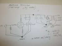
As visuals work best for me, and maybe for someone else too, I started drawing a way of earthing a simple tube buffer. Only high tension, rectification, smoothing and the cathode follower are drawn for simplicity.
I hope someone can point me to mistakes or failures.... Is this the way to do a star-ground? Am I missing something?
I hope this helps this thread as well...
Kind regards, Stef.
I hope someone can point me to mistakes or failures.... Is this the way to do a star-ground? Am I missing something?
I hope this helps this thread as well...
Kind regards, Stef.
Attachments
Two serious problems with that diagram:
1. no connection between star 1 and star 2.
2. star 2 guarantees the injection of charging pulses into the PSU ground.
The solution is to turn star 2 into a bus. The order along the bus is
rectifier -ve out
reservoir cap -ve
smoother cap -ve
connection to safety ground
connection to star 1
Note that star 1 could be a bus too, but it doesn't have to be.
Thank you SY,
Much appreciated! If I understand correctly, star 2 being the PSU ground, can be a buss with a specific order of attaching the components.
I drew it to get it clear, but now I wonder where to connect the 'house-ground' prong of the IEC inlet.
But perhaps I got it mixed up again, care to fill in the dots?
Kind regards, Stef
Attachments
Well, it has never failed me.That is not the way to twist a pair of wires. But it is quick and wrong !
Use your hands to twist the wires and allow the individual cores to rotate in the opposite direction to your twisting direction.
It is this contra-rotating turn of the cores that allows the twisted pair to form correctly.
I usually use a door knob to anchor the fixed end, but a bench mounted vice would do a better job.
Can you explain what the downside to the power drill method is?
.:Sent by pneumatic tubes
No. 'Star 2' must be a bus, not "can be". Your diagram looks OK now.Phats said:If I understand correctly, star 2 being the PSU ground, can be a buss with a specific order of attaching the components.
At first many apologies, DF, I really dont know why I replied with SY. But I can be very distracted sometimes... And I was trying to think really hard... Partly because I was a bit frustrated in not being able to divide the PSU and audio returnpaths. Why can't we do that?
Good to know this diagram looks okay now, but I figure the inlet 'house' prong must be connected directly to the chassis. (combined with safety ground). Is that correct?
Can you explain why the PSU earthing must be a buss?
Kind regards, Stef.
Good to know this diagram looks okay now, but I figure the inlet 'house' prong must be connected directly to the chassis. (combined with safety ground). Is that correct?
Can you explain why the PSU earthing must be a buss?
Kind regards, Stef.
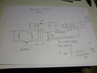
I thought it would be practical to draw DF's comments into a complete visual, hoping it would be of use to anyone. (for me it is!)
"Revised Earthing #2" is how DF commented my diagram and #3 is my deviation, an alternative. The idea is to use the input RCA's groundlug (isolating that input from chassis) as a point for star-ground 1. I read in Bruce Heran's article on grounding and shielding techniques he combined signal and PSU at that point.
Does this work in theory, I can imagine that routing this in practice is quite inconvenient.
As an extra alternative, what are peoples thought on 'buss-grounding' contrary to 'stars'. I mean, routing one bare rod from input to output groundlugs. And (of course I am talking P2P wiring) per stage joining the negative leads to one point, nearest to that stage, at that buss.
Feels more practical to me, but are there drawbacks in that method?
Kind regards, Stef.
Attachments
Stef,
Thanks for taking the time and writing a schematic that shows the physical layout of a star grounding pattern.
Actually, if you read my first post - this is exactly what I said.
To add what Mach1 said, there should be a pair of Ying and Yang diodes
in parallel with the cap and resistor that connects audio ground and hydro earth.
Also, there is series of articles called The Value Wizard. One of the articles is on heaters.
The Valve Wizard
The author says "Rule number one is that the heater supply must always have a DC connection to audio ground."
Actually, the picture of the Mambo amp, shows how to "lift" the heaters using a voltage divider and B+ (if lifting them is required).
.
Stef,
Thanks for taking the time and writing a schematic that shows the physical layout of a star grounding pattern.
Actually, if you read my first post - this is exactly what I said.
To add what Mach1 said, there should be a pair of Ying and Yang diodes
in parallel with the cap and resistor that connects audio ground and hydro earth.
Also, there is series of articles called The Value Wizard. One of the articles is on heaters.
The Valve Wizard
The author says "Rule number one is that the heater supply must always have a DC connection to audio ground."
Actually, the picture of the Mambo amp, shows how to "lift" the heaters using a voltage divider and B+ (if lifting them is required).
.
Please look at your tube data and calculate if you exceed the heather to cathode max potential. Otherwise don't bother raising HT voltage. DC, AC it is all crap!!! I wire everything with AC. The trick is to keep it away from amplifification line, use decent tubes (not old used junk) and pay attention to twisting the wire properly, phasing to cancel from the power stage down to the input tubes. Your AC heathers, in other words, *should* first power the most heather hungry tube, then smallest tube last.
Star ground at input... idk... may work... usually better to place it near the biggest power supply capacitor,
I usually connect the signal and mains ground (chassis) using pair of high current yin-yang diodes.
Actually, I had these MUR415 ultra fast diodes kicking around.
They are rated at 4 Amps - Is their current rating high enough ?
Ditto, but with a small R (typically 100R or so) and a small C (1nF) in parallel with the diodes.
The article Stef pointed out
Grounding and Shielding for your DIY Audio Projects
says
Most methods of making the connection involve resistors, capacitors or rectifiers. I suspect all will work.
My preference is for a parallel combination of a metal film resistor of about 120 ohms (1/2 Watt is fine)
and a type X2 capacitor in the range of 0.1 to 0.22uF. Type X2 capacitors are rated for use with AC mains circuits.
I have seen ceramics and polys used there but since they are not usually AC mains rated I strongly recommend against them.
The capacitor and resistor provide sufficient isolation between the chassis and circuitry to allow the chassis to be an effective EMI shield
but not induce the EMI into the active circuitry.
So the author uses an AC rated cap in // with a 120R resistor rated at 1/2 Watt.
At line level I have never had any issue with using a bolt through the chassis as a grounding point for the circuit - just keep it away from the safety earth chassis point and run a cable between them.
Its an interesting exercise to poke around the surface of a metal chassis with a scope probe and see how much difference there is from point to point - but the important point to remember is that if you have done your star ground correctly all the wires are guaranteed to be at the same potential which will mean that the chassis eddy current effect all ground equally - which effectively means not at all.
Shoog
With #3 you have "extended" the main input stage current loop all the way the the input RCA and back. ie the connection between the last Power Supply capacitor -ve and the cathode resistor. This will increase the chance of this loop picking up noise. I think you are beginning to understand that good grounding is not about having a rigid set of universal rules and more about understanding where the current is flowing and wiring your circuit accordingly using the most appropriate grounding system for each section.I thought it would be practical to draw DF's comments into a complete visual, hoping it would be of use to anyone. (for me it is!)
"Revised Earthing #2" is how DF commented my diagram and #3 is my deviation, an alternative. The idea is to use the input RCA's groundlug (isolating that input from chassis) as a point for star-ground 1. I read in Bruce Heran's article on grounding and shielding techniques he combined signal and PSU at that point.
Does this work in theory, I can imagine that routing this in practice is quite inconvenient.
As an extra alternative, what are peoples thought on 'buss-grounding' contrary to 'stars'. I mean, routing one bare rod from input to output groundlugs. And (of course I am talking P2P wiring) per stage joining the negative leads to one point, nearest to that stage, at that buss.
Feels more practical to me, but are there drawbacks in that method?
Kind regards, Stef.
A resistor divider qualifies as a DC path to ground. I suppose I should re-write that rule as "rule number one is that the heater supply must not be left floating".The author says "Rule number one is that the heater supply must always have a DC connection to audio ground."
Actually, the picture of the Mambo amp, shows how to "lift" the heaters using a voltage divider and B+ (if lifting them is required).
You don't need ground lift components in an intermediate preamp, only the power amp. Just connect audio ground to chassis. This should be done at the furthest possible point 'downstream' of the power supply. In a dual-mono construction this is the audio input jack. If the power supply is shared between L and R channels, then the chassis connection should be at the point where the PSU ground splits to feed the two channels (it may then be beneficial to connect a 100nF ceramic cap between each audio input jack and chassis).Actually, I had these MUR415 ultra fast diodes kicking around.
They are rated at 4 Amps - Is their current rating high enough ?
#3 means longer wires, and is unnecessary. Go with #2.Phats said:"Revised Earthing #2" is how DF commented my diagram and #3 is my deviation, an alternative. The idea is to use the input RCA's groundlug (isolating that input from chassis) as a point for star-ground 1. I read in Bruce Heran's article on grounding and shielding techniques he combined signal and PSU at that point.
Does this work in theory, I can imagine that routing this in practice is quite inconvenient.
All real stars are in fact a short bus. The advantage of a 'star' is that you don't have to think so much. I prefer to use a bus.As an extra alternative, what are peoples thought on 'buss-grounding' contrary to 'stars'. I mean, routing one bare rod from input to output groundlugs. And (of course I am talking P2P wiring) per stage joining the negative leads to one point, nearest to that stage, at that buss.
Feels more practical to me, but are there drawbacks in that method?
Yes, and explain that simply putting a capacitor from heater to ground does not overcome floating. I have been surprised how many people think that it does.Merlinb said:I suppose I should re-write that rule as "rule number one is that the heater supply must not be left floating".
Last edited:
Trying to get more grip on the subject;
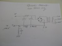
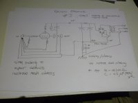
As Merlin explained in a 'dual-mono' or 'shared-supplies' approaches I got back to drawing and I hope to have it right...
So, attached are two versions, one is a 'dual-mono supply' and the second is the 'shared supply'.
But, as drawing, I started to wonder about the connections in safety-ground. In both versions there are a couple of connections on the chassis; first the 'house-prong' connection. Secondly, the PSU connection and third, (in the shared-supply' version) the connection to the input RCA ground-lugs). As far as I have understood, that could lead to potential currents in the chassis?.
I did not completely understand Merlin's suggestion of his addition of small c's at the input RCA's, my best guess is from groundlug to chassis.... Am I correct?
Kind regards, Stef
Ps. for Uunderhill another link (Merlin's page about this subject): http://www.valvewizard.co.uk/Grounding.pdf
That's a great read, when I saw your enquiry I remembered that pdf and went looking for it. But I failed to find it................
Ps. for Uunderhill another link (Merlin's page about this subject): http://www.valvewizard.co.uk/Grounding.pdf
The big message to get from that is:
identify the signal current route and loop. Make that loop interference resistant by making it VERY LOW LOOP AREA.
Do that "identify and make small" for EVERY signal loop, even the output signal and the Power signal/current.
- Status
- This old topic is closed. If you want to reopen this topic, contact a moderator using the "Report Post" button.
- Home
- Amplifiers
- Tubes / Valves
- Star Grounding for a Line Stage Tube Preamp