The output of a transformer can be predicted with just a few bits of the manufacturers' data and one formula.
Output DC voltage after smoothing with no load on the output is given by Vdc = [Vmains / Nominal Vmains * rated Vac of secondary * (1+transformer regulation) * sqrt(2) ] - [diodes Vdrops at near zero diode current].
For a 9.5% regulation 230:15+15Vac transformer running on 236Vac with ordinary bridge rectifier.
Expect the prediction to give
{236 / 230 * (15+15) * (1+0.095) * 1.414} - {2*0.5} ~46.7Vdc
With the correct information the application of the formula allows the model to predict the expected DC voltage. It really is that simple.
Thank you Andrew.
You made it very clear as usual
")
But i have sme questions:
What is the relation between Efficiency and regulation ?
I have a 230V toroid with 89% Efficiency
Last edited:
That efficiency will be quoted for one output power only.
Similarly the transformer regulation is stated for one output power only. The regulation applies to the ratio between maximum rated output power and zero output power.
The efficiency of a transformer varies markedly over the output power range.
Similarly the transformer regulation is stated for one output power only. The regulation applies to the ratio between maximum rated output power and zero output power.
The efficiency of a transformer varies markedly over the output power range.
I can not find any information about regulation in the TX specs I normally use.
I know the lower the value the best, but to have a low percentage of regulation factor, the number of turns in the primary must also be very low.
What should be the average number for a R-Core 120VA 220V to 30V TX ?
I know the lower the value the best, but to have a low percentage of regulation factor, the number of turns in the primary must also be very low.
What should be the average number for a R-Core 120VA 220V to 30V TX ?
Finally getting round to wiring up the bib to power my Optivol board and wondered does the regulator need connecting to chassis ground and if so where is the best place on the reg pcb to connect to? Thanks
Found it post 369
I used a 9Vac secondary to give me the 5Vdc output and used a 6R8 resistor to achieve 198ma[1.34V drop] with 3 green led's. Everythings runs warm but you could hold your finger on things all day. Still sounds good.
Last edited:
correction to post
regulation applies to the voltage ratio between maximum rated output power and zero output powerThe regulation applies to the ratio between maximum rated output power and zero output power.
With a tx 9VAC 30VA could I get 5V 1A?
R301 1R5
Vref 1K trimmer + 1 red LED, other parts jumped
I can't reach 5Vout
?Have I to connect 1K resistor in R303 (Vref area)?
BiB Kit reference voltages Blog started
Hey there, for those of you who have completed target voltages and current, I have created a blog entry to centralize the parts lists needed. Please, please add your stuff into the blog, so others have a place to look get an idea of what parts they need for a particular project.
You can either add to the blog in a reply, or PM me the stuff, and I will edit it into the ugly main page...
Here is the URL
http://www.diyaudio.com/forums/blogs/tea-bag/743-bib-kit-reference-voltages.html
30VA / 9Vac = 3.3Aac.
Max continuous DC current from a capacitor input filter is 3.3 / 2 = 1.67Adc.
Your 1A will use up 60% of the maximum continuous rating.
9Vac * sqrt(2) * ~1.3 (regulation) * 0.94 (mains low voltage) - bridge rectifier ~ 13.5Vdc.
Vdrop to output voltage ~8.5V
What's the problem?
Max continuous DC current from a capacitor input filter is 3.3 / 2 = 1.67Adc.
Your 1A will use up 60% of the maximum continuous rating.
9Vac * sqrt(2) * ~1.3 (regulation) * 0.94 (mains low voltage) - bridge rectifier ~ 13.5Vdc.
Vdrop to output voltage ~8.5V
What's the problem?
Now current adjust resistor 1R5 voltage drop 4.09V current 2.7A enough for the E-MU.
Before current adjust resistor 2R2 but can't get 1A need because E-MU only lit the ON LED & with AC wall adaptor more LEDs lit.
When E-MU switch is OFF Vref red LED lit strong but when switch the E-MU to ON the red LED lit light.
Very difficult to measure what the E-MU really draws.
Before current adjust resistor 2R2 but can't get 1A need because E-MU only lit the ON LED & with AC wall adaptor more LEDs lit.
When E-MU switch is OFF Vref red LED lit strong but when switch the E-MU to ON the red LED lit light.
Very difficult to measure what the E-MU really draws.
Did you jumper the resistor position? You got to check 2 things. 1. The connections of the 4 wires and the polarity of the Emu plug. 2. The current it needs. Else we can not guess.
1. Polarity 4 wires connection checked: was correct.
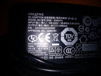
2. shunt reg 2.7A it's enough device max power consumption 1A see attached pic of wall psu supplied with the E-MU
Attachments
- Home
- Amplifiers
- Power Supplies
- SSLV1.1 builds & fairy tales