Make R103 half by paralleling one same or there about. Just in case its too high for the available IDSS by chance and it shoots equalizing IN and OUT. If its not that also look for smaller problematic semis like no good Vbe showing BJTs (0.6-07V is good) or JFETs measuring open or shorted with the Ohm meter across (power off first). The film cap is alright you did not poke through its jacket.
Replaced R103 on left positive with 4K and now it will adjust. Here are my latest measurements. The ground to source voltages are strange on the left channel both boards.
Right Channel
Positive:
Output=24
R101 Vdrop =0.32
V Ground to Source =28.5
Q101 VGS=9.8
Negative:
Output=24
R201 Vdrop=0.26
V Ground to Source =28.4
Q101 VGS=5
Left Channel
Positive:
Output=24
R101 Vdrop=0.24
V Ground to Source=3-6 varies
Q101 VGS=8.6
Negative:
Output=24
R101 Vdrop=0.28
V Ground to Source=12.3
Q201 VGS=5
So it was the first guess. R103 too much in value for a given Q103 sample's IDSS.
We see that all sections regulate at 24V now. By their 10 Ohm R101 R201 set resistors drops we also see that all regs are running only 24mA-32mA CCS unless I don't remember well what you use and the set resistors are 1 Ohm instead thus running 240mA-320mA and able for 150mA load consumption peaks with ease.
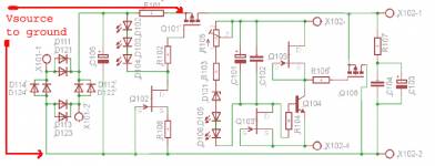
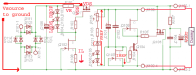
Q101 Q201 source pin to ground can only be Vin (i.e. the VDC across C105 C106 reservoir capacitors) minus VR101 VR201 drop when the regulators are trimming Vout OK below Vin.
And they do trim at 24V. Small value erratic source to ground readings in the minus regs don't explain how they do output 24V. Unless its oscillation reaction to the probing.
We see that all sections regulate at 24V now. By their 10 Ohm R101 R201 set resistors drops we also see that all regs are running only 24mA-32mA CCS unless I don't remember well what you use and the set resistors are 1 Ohm instead thus running 240mA-320mA and able for 150mA load consumption peaks with ease.
Q101 Q201 source pin to ground can only be Vin (i.e. the VDC across C105 C106 reservoir capacitors) minus VR101 VR201 drop when the regulators are trimming Vout OK below Vin.
And they do trim at 24V. Small value erratic source to ground readings in the minus regs don't explain how they do output 24V. Unless its oscillation reaction to the probing.

Alright then. Lets focus to goals now. We look for 2V or more across the 10 Ohm CCS setting resistors in every section as the VDC across the reservoirs must be kept at least 29V when all sections can be set to 24V output voltage. At 100% mains that is. The dummy loads must be no less than 150 Ohms

Explanatory note for later. Fine kids by the way ")
Q101 develops few volts VGS when current runs through it. The LEDS develop forward voltage drop when IL current runs through them and lights them up. Its provided by Q102. VF LEDS (x3 or x4 total) - VGS = VR.
In words the voltage across the setting resistor is the difference of the MOSFET'S gate to source drop VS the drop from all the LEDS. Thus the resistor value restrictively controls the constant current. Hence ICCS = VR / R.
IL mA value can be verified as mV drop across R108 divided by its Ohmic value. Varies a little between Q102 samples due to IDSS tolerances. Q101 Vsource to GND can only be VDC C105 - VR.
Gate stopper R102 makes no drop since healthy MOSFETS do negligible gate current. All those parameters must make sense when measuring.
I.e. four green LEDS should drop no more than four times their ~nominal Vf voltage for instance (near 8V). A 9610 or 610 MOSFET running 200mA to 300mA should develop VGS of 4-5V according to its datasheet.
A 10 Ohms R101 or R201 resistor should show 2-3V across it when such 200-300mA current runs through it. The dummy load should be calculated not to absorb more current at target VOUT than the target CCS current level. Just shy to that in fact for the shunt part of the reg to can barely work. Beyond there it starves. We usually calculate the dummy to represent the peak consumption of the final real life load i.e. a specific preamp etc.
The voltage across the CCS MOSFET (Q101 VDS) should be 5V or more to work well as CCS. Set at 20V output for instance. Does the CCS wake up for current draw? If yes you need a higher transformer or lower voltage to your preamp if its happy with lower VCC also. If transformer secondary VS VOUT margin is restrictive short the fourth green LED and piggyback another 10 Ohms on R101 R102 to save 2 Volts margin or so.
Attachments
1.1 with IRF9640 in both MOSFET positions for the positive polarity branch and big sinks when the amplifier's peak power current draw just before clipping has been measured (or having asked the manufacturer) and the CCS setting covers it with say at least 100mA spare. Also oscilloscope rail check for interference on the rail from the amp's chips when in four wire mode to determine if its better to use it in two wire mode.
TeaBag does not have IRF9640, only IRF610.....can IRF610 be used??
What are the performance differences between the 610 and the 9640 please??
Or is it still better to use IRF9640??
- Home
- Amplifiers
- Power Supplies
- SSLV1.1 builds & fairy tales