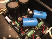
DCB1 PSU was tried some years back for T-amp with good results. DCB1 is family but has some differences and bigger power MOSFETS. There are stronger TO-220s for 1.1 though.
http://www.diyaudio.com/forums/power-supplies/153484-using-hypnotize-general-shunt-reg-pcb.html
read posts #20-29
http://www.diyaudio.com/forums/power-supplies/153484-using-hypnotize-general-shunt-reg-pcb.html
read posts #20-29
Is DCB1 PSU board available from Tea Bag ??
Yes
DCB1 PSU was tried some years back for T-amp with good results. DCB1 is family but has some differences and bigger power MOSFETS. There are stronger TO-220s for 1.1 though.
http://www.diyaudio.com/forums/power-supplies/153484-using-hypnotize-general-shunt-reg-pcb.html
read posts #20-29
Salas....I have read through what you have suggested, but still a bit confused......with V1, V2, DCB1...etc...etc...
Appreciate if you could summarize what is now best PSU for T-2024 or T-2020 please......thankyou.
1.1 with IRF9640 in both MOSFET positions for the positive polarity branch and big sinks when the amplifier's peak power current draw just before clipping has been measured (or having asked the manufacturer) and the CCS setting covers it with say at least 100mA spare. Also oscilloscope rail check for interference on the rail from the amp's chips when in four wire mode to determine if its better to use it in two wire mode.
I'm having problems with the left channel regs. The output reaches 24V at about 85% on the variac and turning the trimmer in either direction has no affect. This is the same on both positive and negative regs. All LEDs light up.
Vdrop=.05
ground to source pin at Q201=20v
VGS=2.9
Vdrop=.05
ground to source pin at Q201=20v
VGS=2.9
Measurements
Now only one positive reg won't adjust. Here are the measurements I took at 100% mains on all four regs:
Right Channel
Positive:
Output = 24V
R101 Vdrop = .32
V Ground to Scource = 28.6V
Q101 VGS = 9.7V
Negative
Output = 24V
R201 Vdrop = .25
V Ground to Scource = 28.5V
Q101 VGS = 5V
Left Channel
Positive ** This is the reg that won’t adjust
Output = 29V
R101 Vdrop = .05
V Ground to Scource = 26.5
Q101 VGS = 10.4
Negative
Output = 24V
R101 Vdrop = .28
V Ground to Scource = 25
Q201 VGS = 5V
Shows from the very small Vdrop in the problematic one. It will probably need a new q101. Also the q101 vgs is unusually high in both positives. Maybe you got a dodgy batch of 9610s?
@Salas
C102,202,302,104,204,304 4,7uF-10uF/63V MKT
4,7uF is the min. value?
TIA
Felipe
Min value yes
What's happen if I use more of 10uF or less of 4.7uF?
Shows from the very small Vdrop in the problematic one. It will probably need a new q101. Also the q101 vgs is unusually high in both positives. Maybe you got a dodgy batch of 9610s?
Replaced Q101, same results. I've had 9610s in the circuit from two different sources with same results.
The only physical difference in the problematic one is where I melted the side of the output capacitor taking mosfets in and out. Could this be the problem?

- Home
- Amplifiers
- Power Supplies
- SSLV1.1 builds & fairy tales