Yes they are numbered in that way so to be the same positions. You can use soldered jumpers under the board at the connector pins if for permanent two wire mode use. That way the screws will be free from jumpers. 1 or 3 will represent (hot) hookup screws while 2 or 4 will represent GND hookup screws. Keep close proximity to the load board and thick enough wires to it when in classic two wire mode.
Thanks...
What is advised, how long could be wires in ''two wire'' mode ?
(I think I will have something like 15cm or so....I belive thay will be less than 20cm in worst case )
no, not that much...
it was a mass on the flor and my girlfriend try to clean it up a little
I didn't notice that in that proces some wires get lose so I power it up...the led's did go on and off (while I try to measure voltage)..a then off for good
I have some spare Q203-205, so I will just change tham...
Aha! So there was a saboteur involved after all
*Remember Q204 is PNP by the way. Lets hope it has not done more parts or a MOSFET also. We will see
could you please post some picture, as I'm building regulators for Najda too...
thanks
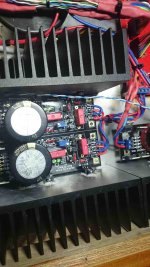
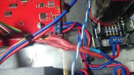
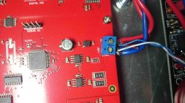
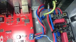
Here you are Yoke. I also recommend running heatsink mount resistors for R101, 201, 301 as these can get quite hot if using normal types. I ran 2 wire shunt on the +,- 12v boards and ran using shunt on the 5v. Note also the +- on the 5 v supply seems to be labeled wrong on the najda boards I used. Red wire to +5v, blue to Gnd 0v.
On another note, I do hope one day to visit Croatia and Split. My father was from Croatia so I have to visit the relatives some day.
Cheers
Simon
Attachments
Aha! So there was a saboteur involved after all
*Remember Q204 is PNP by the way. Lets hope it has not done more parts or a MOSFET also. We will see
jea
there were two choices, cleaning up a little or trowing trough window
I believe this was less damage
will do so Sales tnx
Here you are Yoke. I also recommend running heatsink mount resistors for R101, 201, 301 as these can get quite hot if using normal types. I ran 2 wire shunt on the +,- 12v boards and ran using shunt on the 5v. Note also the +- on the 5 v supply seems to be labeled wrong on the najda boards I used. Red wire to +5v, blue to Gnd 0v.
On another note, I do hope one day to visit Croatia and Split. My father was from Croatia so I have to visit the relatives some day.
Cheers
Simon
Hi Simon,
thanks,
but now that I see yours pictures, you got me worried,
I have just place/screw regulator mosfets to the bottom of aluminium case which is 5mm thick.
but now I see that you have use heatsinks that good enough for colling aleph mini
I know thay will produce heat...but...will see
there is no place inside my cabinet for heatsinks
so will have to see once I power it all up...
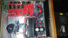
here are some pictures of my Salas (for Najda +/-12, +5V) + Najda (I2S)+ 3xAYAII DAC (I2S) + 6 channel P1.7+ 6 channel RelVol3


If you came to Split, give me a call
it's nice town
Last edited:
Hi need help here, just finished a pair of positive/negative, the neg looks OK, but not pos, D105, D106 (red LED) turned on, D102(a,b), D103(Green LED) were not, (jumper on D104), the Q106 was extreme hot, but I can adjusted it to the voltage I want (+12V), what the problem could be? Thanks
Check the green LEDS for either broken or reversed unit(s) first. Try to light them up with DMM if it puts out enough voltage in diode mode or with a 9V battery and 1K in series. Touch them with the probes while they are soldered in. No need to get them out for just checking. If the problem is not the LEDS turn to Q101. Inspect its insulation also. Less likely to be about Q102 but if the MOSFET is alright check Q102 JFET also.
Check the green LEDS for either broken or reversed unit(s) first. Try to light them up with DMM if it puts out enough voltage in diode mode or with a 9V battery and 1K in series. Touch them with the probes while they are soldered in. No need to get them out for just checking. If the problem is not the LEDS turn to Q101. Inspect its insulation also. Less likely to be about Q102 but if the MOSFET is alright check Q102 JFET also.
problem solved, it's green LED, not sure why all 3 were broken, maybe something went wrong during initial started up?
I can tell you that about month ago I was finishing my nixie clock and I got about 20 LEDs batch for illumination of tubes. Every single one LED was dead after soldering. Whole batch was trashed. I use 2 old (still made in US) but very nice Weller Stations (15w and 40w) and never got such troubles with heat damage. You might have same bad LEDs.
Sent from my iPhone using Tapatalk
Sent from my iPhone using Tapatalk
problem solved, it's green LED, not sure why all 3 were broken, maybe something went wrong during initial started up?
Unless you reverse high enough voltage polarity across them you can't break them electrically in there with the recommended range of transformers. They either can be installed in reverse or overheated during soldering. They are some times much heat sensitive. Probably too long time under the iron or too sensitive a batch.
*Q102 keeps their current low and steady in normal polarity and can stand 50V DC. Check drop across R108. If its something like 20-100mV then Q102 still does its job.
I am planning on building a BA-3 pre using the SSLV regs. I intend making a dual mono setup with a transformer and a set of + and - boards for each channel. Output 24V DC with load per phase of about 65ma, current setting 200ma.
The guide suggests a transformer that for DC is 7-10V extra. I am planning on buying the transformers from Antek and can get either 22 or 24V secondaries with either 50VA or 100VA capacities. They are all similarly priced. The voltage at my place is 121V. Which of the four would you recommend?
thanks. Nash
Hello Nash
I would recommend the 24V AC model
Thanks Salas. I will go with two 24V transformers. 100VA or 50VA?
50VA each are OK
Great! Thanks. Two 24V 50va it is. Now to wait for the next GB to close since Tea-Bag is presently out of boards.
A simple question regarding the SSLV.
Is it ok to place the trafo and SSLV in one case and the circuit it is powering (in this case a preamp) in a another case?
Or does the reg work better if I run really short wires to the preamp? I could put the trafo and diode bridge/smothing caps on the PSU case running DC to the regs on the "audio case".
Umbilical cable would be around 3 feet.
Any reg works better with short cables to the preamp. This one will save you the cable resistance problem if used in four wire mode but long output cabling may still mean interference danger. So, if you can, avoid it. I.e. make the second option.
Thanks!
I have all my regulators build and tested ...all working
But have one question ;
As my plan is to use it with DSP is it problem if it goes to stand by mode ?
(As I remember regulators should always have some load on output, and at stand by this load is very low)
Also have one pcb and transformator so I could build power suplay for relay attenuator and it also have stand by...( it needs like 1A or more with 5V at full load...and very low consumption on stand by)...i know it doesn't make sense to use regulator for it..but have spare parts ...and its easy build)
...all working But have one question ;
As my plan is to use it with DSP is it problem if it goes to stand by mode ?
(As I remember regulators should always have some load on output, and at stand by this load is very low)
Also have one pcb and transformator so I could build power suplay for relay attenuator and it also have stand by...( it needs like 1A or more with 5V at full load...and very low consumption on stand by)...i know it doesn't make sense to use regulator for it..but have spare parts ...and its easy build
)- Home
- Amplifiers
- Power Supplies
- SSLV1.1 builds & fairy tales