Hello Salas.
I turn to a power supply of 18,5V to power the clock XO2.2 of tentlabs.
* My question is: I measured the circuit and consumes 180mA. With that current range I calculate the SLV1.1 mosfet ¿250mA?
** Thanks and greetings from Spain ...
Greetings from Athens
As Merlin said 250mA-350mA total available current should be nice for your application
The goal is to simulate the situation with the final application. What portion of that total represents the expected load current demand? You plug that figure to Ohm's law solving for resistance. Example: You need 150mA at 24V for a preamp so R=V/I 24V/0.15A=160 Ohm
Since voltage with current produce heat you would want a resistor that could take 24*0.15=3.6W (choosing higher spec in practice since power resistors get too hot if their nominal power spec is very near to the dissipation we excercise on them)
Since voltage with current produce heat you would want a resistor that could take 24*0.15=3.6W (choosing higher spec in practice since power resistors get too hot if their nominal power spec is very near to the dissipation we excercise on them)
Thank you Massimo.
If you will spend the total current on the dummy load then nothing will be left inside the reg. A common trap. Then the reg can't up enough voltage because its running on empty like that Jackson Browne song in Forest Gump.

The dummy MUST represent the final real load needs only which are a portion of the total CCS we set for nice hot-rod performance.
Thus 24/0.045=533 > 560ohm
and 24*0.045=1 > 3W
Thank you Salas. The preamp is the Pass BA3 which runs at +- 45ma so I guess I am aiming a little high.
Its not bad to use much spare current since hot-rod enhances the output impedance spec by "massaging" the MOSFET better. The thing to weigh is dissipation on sinks. Because that extra is going to burn on the sinks. Massimo's correct calculation of a dummy representing only 45mA @ 24V comes handy again, so when testing for that near real load consumption you evaluate the heat on sinks realistically too and you decide how high you can set the CCS for balance between hot-rod and acceptable heat given your sinks size, box size, and ambition.
Whoops I have just connected up one channel of the BA3 preamp after setting the regulators to give the req'd 24vdc; turned on only to realise that I had connected the 0 and S- crossed the two leds in trimmer section did not light up. What damage am I likely to have done down stream of the SSLV?
With the BA3 disconnected and the dummy load reinstalled the regs seem to be ok and still give 24V output.
I have just connected up one channel of the BA3 preamp after setting the regulators to give the req'd 24vdc; turned on only to realise that I had connected the 0 and S- crossed the two leds in trimmer section did not light up. What damage am I likely to have done down stream of the SSLV?With the BA3 disconnected and the dummy load reinstalled the regs seem to be ok and still give 24V output.

I do silly things like this as well.Whoops
With the BA3 disconnected and the dummy load reinstalled the regs seem to be ok and still give 24V output.
That's why I recommend the protection diodes across the supply rails at the DC power input to the circuit PCB. It has saved my amps a few times. The bulb just turns on and the circuit sees a maximum reverse voltage <1Vdc.
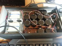
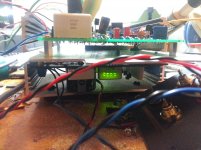
Salas, thanks for your great design, its totally stable and sounds great running my Dynalo. Dynalo uses around 150mA for two channels in class A. The shunt is running at around 350mA. I used 4 diodes as you recommended somewhere.
The pre reg is +/- 22V medical grade transformers, not sure if that matters.
Its a cap multiplier. Now some audio porn. Should probably have waited till waited till the housing is finished, but wanted to share.
The pre reg is +/- 22V medical grade transformers, not sure if that matters.
Its a cap multiplier. Now some audio porn. Should probably have waited till waited till the housing is finished, but wanted to share.
Attachments
- Home
- Amplifiers
- Power Supplies
- SSLV1.1 builds & fairy tales