When you take a reading say at the grid of the 12AT7 good channel compare it with the reading on the non working channel 12AT7 grid and see if they match and so on and so forth and see if every point on both channels are the same. When you run across the point that has a different reading than the good channel you have made progress.
Then you can do the same thing with voltage readings both DC and AC and compare. You have one channel you know is good so compare impedance and voltage readings between each channel. You are going to find something, voltage or resistance, that is not the same as the good channel. Then you will have localized the trouble then start looking at those components in that part of the circuit.
I did a checkout procedure yesterday for both and it all checked out. Is it the same procedure you mention? used Ty Bowen's instructions.
Today, I replaced 3 caps for the right channel as well as the CCS - same results as before, either rattling noise on the right channel without input, or else just very low rumbling.
Double check values for r10 13 14 and 19
I guess that's going to be one of my next steps. I can replace these.
Have you tried taking the soldering iron and going over all the connections on the bad channel? Worth a shot and is quick and easy. I still say if you take some more measurements comparing the good with the bad channel something should be different. As others have said you may need to take some amp readings as well. If everything is the same it should play. I notice you said you had to turn a tube socket. Is this socket on the bad channel?
The ccs says 10 mA but what does the tube tell you?
Also provide the voltage at each cathode...both 12at7 sections and the kt88s...then also verify it is not above cap voltage ratings.
I am getting more convinced it is a signal path issue...
Thanks a lot for helping, cjkpkg, I will try to get all measurements written down soon.
Have you tried taking the soldering iron and going over all the connections on the bad channel? Worth a shot and is quick and easy. I still say if you take some more measurements comparing the good with the bad channel something should be different. As others have said you may need to take some amp readings as well. If everything is the same it should play. I notice you said you had to turn a tube socket. Is this socket on the bad channel?
Hi wdecho,
this time I didn't reflow all the solder joints.
I believe the socket I had to turn indeed was on the right channel. I checked for continuity on the socket hole and the pads below for all sockets today and they seem OK.
Your left channel is the problem channel correct?
Right channel.
Bad channel same as the one you had to turn the socket, hmm.........I would get a good magnifying glass or better yet a loupe and check the traces on the board very carefully. It is very hard to remove a socket without damaging the traces. I would have cut the pins off of the socket and removed them one at a time and replaced with a new socket. I would be very suspicious of that place on the board and the socket. Persevere the answer is going to seem so simple when you find it.
Bad channel same as the one you had to turn the socket, hmm.........I would get a good magnifying glass or better yet a loupe and check the traces on the board very carefully. It is very hard to remove a socket without damaging the traces. I would have cut the pins off of the socket and removed them one at a time and replaced with a new socket. I would be very suspicious of that place on the board and the socket. Persevere the answer is going to seem so simple when you find it.
Yes, it is hard to do (even George says so), and so was quite disheartened when I found out I had soldered the socket badly.
But, I have 100s of hours under my belt salvaging parts, so I tried it, then built the amplifier.
The amplifier worked the first time it was tested, so I don't think I damaged anything.
This said, if push comes to shove, I will have to diagnose this more fully by checking everything.
Hopefully I make progress on this, tube circuits are not familiar to me, so ideally, if I get step-by-step instructions for checking things, I can do that.
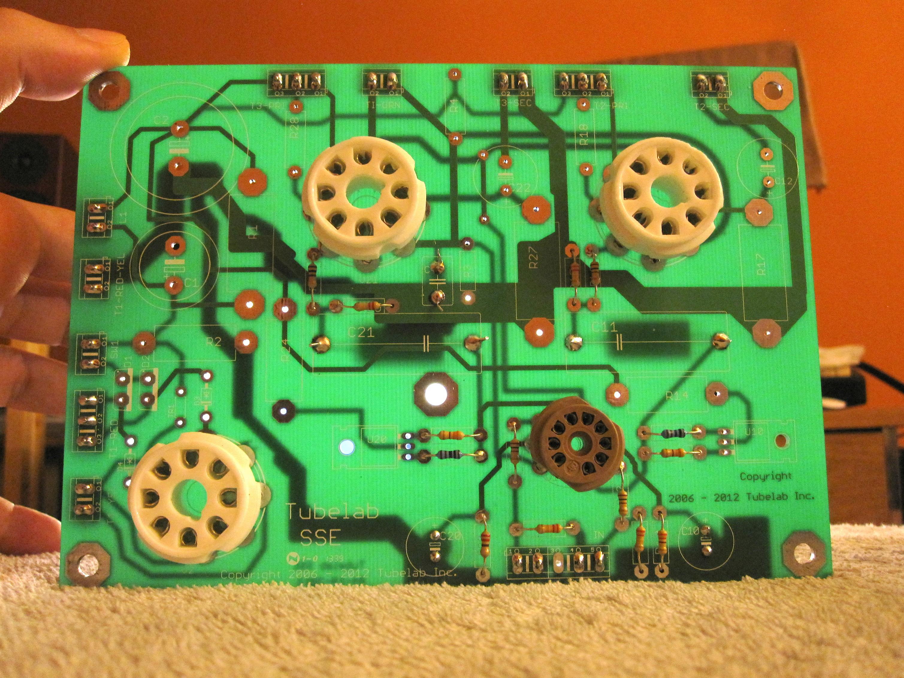
Here's the original pic with the issue on the right:
Last edited:
After checking the board with a good magnifying glass and if it appears to be good why not just replace everything in that channel. The cost is not that great with not many parts. That should have you up and running. Just pull all the parts in the right channel and start over. New correct parts with a good board and it will work. Be sure and check for bridges of solder while you are looking with the magnifying glass. Working good and then failing means something quit working that was working good. An incorrect resistor that is too low would eventually cause maybe the 10M45 to fail or possible a cap. You can sometimes spend more time diagnosing than it would take to just replace everything in one channel especially on a SET with such few parts. 14 components and most of them are cheap resistors.
True, true, and that's why I ordered replacement parts for the right channel, except I hadn't ordered new coupling caps.
Today, I am thinking of replacing the coupling resistor as suggested.
Yes, it is hard to do (even George says so), and so was quite disheartened when I found out I had soldered the socket badly.
But, I have 100s of hours under my belt salvaging parts, so I tried it, then built the amplifier.
The amplifier worked the first time it was tested, so I don't think I damaged anything.
This said, if push comes to shove, I will have to diagnose this more fully by checking everything.
Hopefully I make progress on this, tube circuits are not familiar to me, so ideally, if I get step-by-step instructions for checking things, I can do that.
Here's the original pic with the issue on the right:
Yash...I have given you at least 3 things to check out that will point you in the right direction.
All cathode voltages
12at7 cathode current both channels
Grid stoppers values ...all
Check rating of cathode voltage of cathode bypass caps
Swap opts
Dmm check the coupling caps...remove them to check...I assume you have a Dmm that can test caps.
Don't waste time and money until you do these 6 things and report all readings to us
Doing this will likely pinpoint if it is a hardware issue or signal path issue.
Last edited:
Yash...I have given you at least 3 things to check out that will point you in the right direction.
All cathode voltages
12at7 cathode current both channels
Grid stoppers values ...all
Check rating of cathode voltage of cathode bypass caps
Swap opts
Dmm check the coupling caps...remove them to check...I assume you have a Dmm that can test caps.
Don't waste time and money until you do these 6 things and report all readings to us
Doing this will likely pinpoint if it is a hardware issue or signal path issue.
It sounds like you have much more experience with tube circuits than I do. Listen to him and do what he says first. My way was a newbie way. We all may learn something from his advice. My experience with tube circuits were classes I took 45 years ago. I just started this past year building tube amplifiers.
It sounds like you have much more experience with tube circuits than I do. Listen to him and do what he says first. My way was a newbie way. We all may learn something from his advice. My experience with tube circuits were classes I took 45 years ago. I just started this past year building tube amplifiers.
HA! thanks for the kind words but I would say I have not so much experience as time I have spent troubleshooting...most important thing is that we continue to LEARN something.
These tips were provided to me over the years of building new things. It almost always works out to be something simple that we have overlooked.
Most important next steps is for Yash to post the readings I have recommended he provide.
I guess I am also assuming he knows how to calculate cathode current...maybe not something I should assume...but here it goes...
Take the reading in volts from the cathode to ground. Then divide that value by the ohms of the cathode resistor...
For example if the CCS is supposed to run 10mA, which it is...that means that you should be reading around 2.2volts across the resistor (same as cathode to ground). 2.2/220 = 0.010. V/R=I
If your DMM doesnt read capacitance then you can at lest yank the coupling cap out of the suspect channel and test for continuity.
Yash...I have given you at least 3 things to check out that will point you in the right direction.
All cathode voltages
12at7 cathode current both channels
Grid stoppers values ...all
Check rating of cathode voltage of cathode bypass caps
Swap opts
Dmm check the coupling caps...remove them to check...I assume you have a Dmm that can test caps.
Don't waste time and money until you do these 6 things and report all readings to us
Doing this will likely pinpoint if it is a hardware issue or signal path issue.
Thanks man, your suggestions haven't gone unnoticed, rest assured.

News of the day:
Yesterday, I was checking if swapping the speakers drivers would show whether the right driver was OK or not: I got rumbling on both channels.
So today, I re-swapped drivers: rumbling on both channels...
Did full amp OFF checkout (ohms): noticed varying values on right socket, so I took the opportunity of re-flowing this socket as well as all the sockets and other components.
Did full amp OFF checkout: all OK
Did amp ON checkout: all OK except last high-voltage check on power tube: it looks like if I move the probes a little, the voltage reading varies, so I reflowed this socket again.
Connected everything again and get rumbling on both channels.
I need to check my drivers and my input cables and source for no issues first before delving into the amplifier again. I want to make sure these are OK first.
- Home
- More Vendors...
- Tubelab
- SSE first build, caps and other questions.