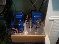
Yup all tubes and depending on chassis might have to be from underneath...or just the bottom of the board....don't over think it
It's not a question of over-thinking it: one is very different from the other, and the one requires me to put the tubes in and ensure I don't break them with the amp upside-down.
It requires me to add a small support in one corner, so that's why it's necessary to know exactly what to do before manipulating my amp as it's extremely heavy: it has 3 large Edcors.
Support it on some books upside down or as cjkpdg says on it's side. Remember one hand in pocket and you have nothing to worry about. Hook up ground first with one hand before turning amp on.
That's how I have it set up, but thanks also to cjkpdg for the other idea, looks feasible as well, although perhaps a little bit less practical IMO in my case.
My gf is here with me writing down the measurements I am making.
Last edited:
Driver Pin measurements with Amp On and tubes in.
Here are the measurements we just gathered with some minimal observations (the test speakers are connected):
P1: 497 VAC and a little 'click' on touching
P2: 2 VAC and some buzz on touching
P3: 5 VAC
P4: 60 VAC
P5: 60 VAC
P6: 505 VAC and a little 'click' on touching
P7: 2 VAC and some buzz on touching
P8: 6 VAC
P9: 60 VAC
The numbers do not seem right to me. P1 should be DC and 497 is high. P4 and P5 should be around 6VAC. I think you just have the AC where it should say DC. Yours is running higher plate voltages than mine for sure. You say one channel is ok so get the readings for the output tubes.
http://www.mif.pg.gda.pl/homepages/frank/sheets/093/1/12AT7.pdf
You should see some discrepancies in the readings on the output tubes.
http://www.mif.pg.gda.pl/homepages/frank/sheets/093/1/12AT7.pdf
You should see some discrepancies in the readings on the output tubes.
Now I think about it and the 9 pin is the 12AT7 those plate voltages are way to high. The plate voltages should be around 200VDC but I am guessing at the precise amount but it should be much lower than the plate voltages of the output tubes you are using. R14 and the CCS circuit should drop the voltage much lower than the plates of the output tubes.
I would pull R14 and check and make sure you are using 10K resistors 3 watts. They should drop the voltage much lower than the 500V you are measuring.
I would pull R14 and check and make sure you are using 10K resistors 3 watts. They should drop the voltage much lower than the 500V you are measuring.
Last edited:
The 10M45 is rated max at 450V and from your reading you have around 500V. I have glanced over the build link trying to find the expected plate voltage for the 12AT7 but I have not found it. I would not think that the R14 and R24 being 10K would drop the voltage down to 200V from the 500V reading you are getting. The electronic gurus can calculate what the V's should be from ohms law but I know it should not be as high as you are getting on the plate of the 12AT7. The SSE is designed to operate at around 450V on the plates of the output tubes.
Yup yup...only heaters are A/C all other measurements need to be in D/C...

Pin 9 lifts the heater voltage from ground to 1/4 B+ so it should read around 100vdc.
Pins 4 and 5 are the A/C heater voltage 6.3vac actually here you measure across pins 4 and 5 with Dmm in A/C
1 and 6 are the plates and yes should be around 250vdc to ground
3 and 8 are the cathodes and should read 2.2vdc to ground
I'd have to dig a little for the grid target...
Last edited:
Yup yup...only heaters are A/C all other measurements need to be in D/C...

Pin 9 lifts the heater voltage from ground to 1/4 B+ so it should read around 100vdc.
Pins 4 and 5 are the A/C heater voltage 6.3vac actually here you measure across pins 4 and 5 with Dmm in A/C
1 and 6 are the plates and yes should be around 250vdc to ground
3 and 8 are the cathodes and should read 2.2vdc to ground
I'd have to dig a little for the grid target...
What do you think is causing such a high voltage on the plates of the 12AT7? The only thing I can think of is that he has the wrong voltage dropping resistors.
The numbers do not seem right to me. P1 should be DC and 497 is high. P4 and P5 should be around 6VAC. I think you just have the AC where it should say DC.
My mistake again.
Can you please tell me for each pin which should measure in AC and which in DC?
Yup yup...only heaters are A/C all other measurements need to be in D/C...

Pin 9 lifts the heater voltage from ground to 1/4 B+ so it should read around 100vdc.
Pins 4 and 5 are the A/C heater voltage 6.3vac actually here you measure across pins 4 and 5 with Dmm in A/C
1 and 6 are the plates and yes should be around 250vdc to ground
3 and 8 are the cathodes and should read 2.2vdc to ground
I'd have to dig a little for the grid target...
Thanks a lot, that's what I'm looking for.
P2 and P7 - Grids: let me know what I should look for here, and AC or DC, thanks.
Last edited:
The only thing I can think of is that he has the wrong voltage dropping resistors.
Hi wdecho, could a defective resistor somehow do that?
The 10M45 is rated max at 450V and from your reading you have around 500V. I have glanced over the build link trying to find the expected plate voltage for the 12AT7 but I have not found it. I would not think that the R14 and R24 being 10K would drop the voltage down to 200V from the 500V reading you are getting.
Sounds like a good diagnosis to me.
Now, just replaced the CCS. Based on the possibility of a defective resistor here and higher plate voltage than normal, there's a fair chance the new CCS is blown as well, right?
I have glanced over the build link trying to find the expected plate voltage for the 12AT7 but I have not found it. I would not think that the R14 and R24 being 10K would drop the voltage down to 200V from the 500V reading you are getting. The electronic gurus can calculate what the V's should be from ohms law but I know it should not be as high as you are getting on the plate of the 12AT7. The SSE is designed to operate at around 450V on the plates of the output tubes.
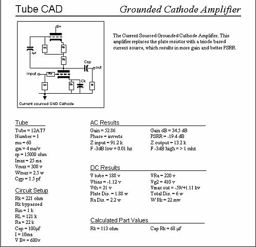
I found this on George's Simulation page for the 12AT7:

The only thing I can think of is that he has the wrong voltage dropping resistors.
Talking about R14, is it necessary to check the surrounding R19 and R13 which work around the CCS?
I do not think so, the R14 and R24 are the ones that drop the voltage down. I would definitely pull the R14 and the R24 and check and be sure you have not installed 10 ohm or 1K ohm ones by mistake. It is a common mistake made by everyone no matter how many builds they have done. The value should be 10k looking at the schematic. You essentially have the full B+ voltage going into the CCS and plates of the 12AT7 which makes me think you have installed 10 ohm instead of 10K ohms.
I do not think so, the R14 and R24 are the ones that drop the voltage down. I would definitely pull the R14 and the R24 and check and be sure you have not installed 10 ohm or 1K ohm ones by mistake. It is a common mistake made by everyone no matter how many builds they have done. The value should be 10k looking at the schematic. You essentially have the full B+ voltage going into the CCS and plates of the 12AT7 which makes me think you have installed 10 ohm instead of 10K ohms.
OK, sounds like the next steps in the plan.
I suppose you're saying to also pull R24 because of the readings I gave above which appear too high, but on the other hand, that channel is working...
- Home
- More Vendors...
- Tubelab
- SSE first build, caps and other questions.
