is Q2 part of the fixed bias fore the 6L6 output ?
Yes, it replenishes spent grid currents to avoid blocking.
In AB2: Q2 maintains bias balance -29.3 by recharging the cap in cutoff.
In AB1: Resistors and caps do the job without help, and Q2 does nothing.
Again, I would up both those coupling caps to 10uF. Forgot to recalculate
the new corners when I upped concertina current to 30mA for driving AB2.
Attachments
Last edited:
Hi
IMO, for a phase splitting circuit made from sand-state, the bridge topology can’t be beat. It may take a few more silicon parts though. What I find when using one transistor and deriving the two signals from the collector and emitter is that the non-equal capacitances of the collector and emitter will shift the phase away from 180 degrees as frequency rises. Any deviation in phase of one from the opposite of the other will result in an awful distortion if these two signals are to be placed across the load as in full bridge output.
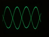
The bridge circuit, being two complementary differential amplifiers will be able to maintain more accuracy in phase matching of the two signals. Here is a circuit I built a while back that works quite well as a discrete phase splitting small signal amplifier. The sign wave here is 1MHz, which is above the -3dB gain frequency, but it is still in phase which means all the AF and harmonics (particularly any common mode distortions: ) are perfectly aligned. Perhaps an integrated approach might be more suitable. The THAT1606/1646 might do the trick.
IMO, for a phase splitting circuit made from sand-state, the bridge topology can’t be beat. It may take a few more silicon parts though.
What I find when using one transistor and deriving the two signals from the collector and emitter is that the non-equal capacitances of the collector and emitter will shift the phase away from 180 degrees as frequency rises. Any deviation in phase of one from the opposite of the other will result in an awful distortion if these two signals are to be placed across the load as in full bridge output. The bridge circuit, being two complementary differential amplifiers will be able to maintain more accuracy in phase matching of the two signals. Here is a circuit I built a while back that works quite well as a discrete phase splitting small signal amplifier. The sign wave here is 1MHz, which is above the -3dB gain frequency, but it is still in phase which means all the AF and harmonics (particularly any common mode distortions: ) are perfectly aligned. Perhaps an integrated approach might be more suitable. The THAT1606/1646 might do the trick.
Attachments
Last edited:
The equal Z concertina doesn't show any shift at 20KHz.
Capacitance definitely represented in Cordell's model.
Distortion as I would expect driving big grid currents.
See attached pic.
Whats yours look like at 20KHz, driving grid currents?
Your part only delivers +/-17.8V. How does it drive 6L6?
Your point, my simple circuit can't possibly do all that?
I just ran again at 1MHz, driving signals still in phase.
In simulation anyways, it still seems to hold its own...
Attachments
Last edited:
Something still wrong with low frequencies though.
Ripple cap C4 wants to be 47uF or more. Bcause ripple
from the supply isn't even the issue anymore. It's the
driving currents, challenging that cap to hold its station.
Vocm enforcement this way is not entirely harmless,
nor impact only during the time and on side of cutoff.
20Hz AB2 is much more a mess than it looks at 1KHz.
Further increase of the coupling cap values seems to
confuse LTSpice. It can't figure valid stating points...
Last edited:
I don't see a way to fix this that doesn't involve at least 2 transistors.
At that point we might as well have used followers, and take a heavy
unreasonable burden off the concertina and coupling caps.
It looked promising, especially as the frequency went higher. But its
not workable if the lowest frequencies can't be played with reasonable
coupling caps, and concertina quiescent less than our output tetrodes.
Might not suck as a guitar amplifier. But I would not care to modulate
more than one instrument at a time though that brand of terrible low
frequency distortion.
Last edited:
kenpeter;3575692 In AB1: Resistors and caps do the job without help..... and Q2 does nothing.[/QUOTE said:from what I understand, AB2 is only a matter of a little exstra peak power
and if I understand this correctly, AB2 won't make any difference at 'normal listening'
You won't find any problem in AB1, or even AB2 with a high pass filter.
This cheat for replenishing AB2 grid currents is nasty at low frequencies.
Didn't run all the scenarios I should have to realize this sooner.
I wouldn't say a "little" extra peak power. More like 50% more, and with
a soft round clip (within its frequency range) that makes wattage before
noticeable onset of distortion even greater.
Resent any suggestion that we are 'normal listeners'.
----
If we stick to AB1, and disallow AB2:
We don't need huge concertina currents.
We don't need huge coupling caps.
We don't need to replenish or buffer charges lost to grid currents in those caps.
Locally equal impedance is pointless, except nice side effect of voltage gain.
But the problem: There is nothing (but maybe huge grid stoppers)
limiting an AB1 amp from operating unintentionally in AB2. Where it
quickly pumps itself off its ideal bias into severe blocking distortion.
And exists no circuit but a slow bleed resistor to recover those bais.
If we speak an amp that intentionally operates only in AB1, but hits
AB2 by accident: Vocm enforcement is turned off except in accident
when the long term blocking distortion would be much worse.
But this also relies on some symmetry that may not exist in case
of AB1 with a single unexpected AB2 peak....
Last edited:
A little feedback from collector Q2 cradles cap recharge much more gently.
Current in the Concertina is up to 45mA, and Q1 near smoking at 5W!!!
Current at plate is not exactly constant anymore, as base current draw
is becoming a significant portion of whats meant to leak through R4.
20Hz AB2 is now possible, not this result makes a whole lot of sense.
Still think the coupling caps should be bigger, but LTSpice won't even
start the simulation if I try. Something may be on the edge of no good.
I havn't checked for stability of the open loop and and all that junk yet...
Attachments
Last edited:
You can add a resistor in series with 12AX7's cathode....
no, I meant ... 'if using cathode bias on output tubes' would help regarding the unreliable bias drift you say is a risk with AB1 ?
What?
I'm not sure what what ?
but isn't cathode bias also called 'auto bias' because it is self regulating
..... But the problem: There is nothing (but maybe huge grid stoppers) limiting an AB1 amp from operating unintentionally in AB2. ....
Its fixed bias. AB can't autobias unless you look for the 30-40mA minimum
average measured across the cathode resistors. I tried that many times but
the pulse seen only at a weak crossing is a little too brief to set an autobias
smoothly. Whats the prob with fixed bias in an AB amp?
average measured across the cathode resistors. I tried that many times but
the pulse seen only at a weak crossing is a little too brief to set an autobias
smoothly. Whats the prob with fixed bias in an AB amp?
Last edited:
- Status
- This old topic is closed. If you want to reopen this topic, contact a moderator using the "Report Post" button.
- Home
- Amplifiers
- Tubes / Valves
- SS phase splitters?