So now you are posting you can't use a Kef B200 with a series crossover and that Fried did not know anything.
Fried used one version of the Kef B 200 in a subwoofer at 6db per octave in parallel. It can also be wired in series configuration. I know from having many of the old plans and knowing people that were involved with the company.
friedmodelh - mpbarney
Fried used one version of the Kef B 200 in a subwoofer at 6db per octave in parallel. It can also be wired in series configuration. I know from having many of the old plans and knowing people that were involved with the company.
friedmodelh - mpbarney
So now you are posting you can't use a Kef B200 with a series crossover and that Fried did not know anything.
Fried used one version of the Kef B 200 in a subwoofer at 6db per octave in parallel. It can also be wired in series configuration. I know from having many of the old plans and knowing people that were involved with the company.
friedmodelh - mpbarney
Hi,
I don't care.
Of course it can be used as a subwoofer with a series x/o.
Your getting very pointlessly boring, say something informative.
I didn't say Fried knew nothing, I did mean he made claims that
are beyond the pale in inaccuracy, intentional or not, just wrong.
rgds, sreten.
Like i've said before, why don't you start your own thread
regarding your version of misguided reality, rather than
banging on about the same garbage in lots of threads.
Last edited:
Misguided reality . When you stated you don't know onions neither did Fried. If Bud were alive he would engage you in a defamation of character civil action.
First you don't answer my questions .
You verbally assault anyone that disagrees with you. I have proof of this.
On Audiokarma you make fun of people who don't agree with your posts.
You make statements that you cannot mathematically prove..
If you were aware of any of the info I stated you wouldn't behave in such an unprofessional manner.
Maybe you should take up a more challenging hobby. Weightlifting, marksmanship or martial arts for you probably might be to challenging.
You have no manners and are a poor role model. I can prove all of my statements. You still have yet to answer my question what happened to the current . You gave me an answer that is incorrect. We are discussing ac current. In a series circuit the current that does not pass through the capacitor goes back to midbass driver. This also happens with the inductor .This is why the negative side of the tweeter is connected to the midbass positive. The high frequencies that do not go through the inductor go back to the tweeter on on it's negative connection. You don not understand these circuits by the posts you have made . You have defamed my character. You claim to be an electrical engineer. I would not trust you to engineer a proper dog poop clean up.
Ken on Audiokarma and many othes have pointed out your errors. I have given formulas on t-line design which are proven design parameters. I have stated examples which are facts that under the rules of law are evidence. You are the one that is technically incorrect. Your own posts is the evidence. You post design and knowledge has moved on . Has OHMS LAW changed.
This is only a hobby to me.
Last edited:
Much of the crossover design theory go back to a long history lesson . A wheatstone bridge is where it all originated. Do you want me to explain it to you., It could take years for me to get you to comprehend it if that is even possible. I can only tolerate so much of your intimidations.
Last edited:
Misguided reality . When you stated you don't know onions neither did Fried. If Bud were alive he would engage you in a defamation of character civil action.
First you don't answer my questions .
You verbally assault anyone that disagrees with you. I have proof of this.
On Audiokarma you make fun of people who don't agree with your posts.
You make statements that you cannot mathematically prove..
If you were aware of any of the info I stated you wouldn't behave in such an unprofessional manner.
Maybe you should take up a more challenging hobby. Weightlifting, marksmanship or martial arts for you probably might be to challenging.
You have no manners and are a poor role model. I can prove all of my statements. You still have yet to answer my question what happened to the current . You gave me an answer that is incorrect. We are discussing ac current. In a series circuit the current that does not pass through the capacitor goes back to midbass driver. This also happens with the inductor .This is why the negative side of the tweeter is connected to the midbass positive. The high frequencies that do not go through the inductor go back to the tweeter on on it's negative connection. You don not understand these circuits by the posts you have made . You have defamed my character. You claim to be an electrical engineer. I would not trust you to engineer a proper dog poop clean up.
Ken on Audiokarma and many othes have pointed out your errors. I have given formulas on t-line design which are proven design parameters. I have stated examples which are facts that under the rules of law are evidence. You are the one that is technically incorrect. Your own posts is the evidence. You post design and knowledge has moved on . Has OHMS LAW changed.
This is only a hobby to me.
Hi,
Your so full of crap :
In a series circuit the current that does not pass through the capacitor
goes back to midbass driver. This also happens with the inductor.
Jesus this is kindergarten stuff, and your terrible at explaining anything.
Of course it does, that how a series crossover works. The current through
the inductor, which isn't the current through the capacitor flows through
the bass unit. Similarly the current through the capacitor which isn't the
current through the inductor passes through the tweeter.
Bleedingly obvious and exactly the same current wise as a parallel x/o,
though unlike parallel at one point the same current passes through
both drivers and no current passes through the inductor/capacitor.
Still the same values though as parallel with resisitive loads.
Current doesn't go back anywhere, according to Kirchoff.
Your just someone that massively overrates what you actually know,
what you know your incapable of communicating accurately / clearly,
and sadly think your best argument is to resort to personal insults.
rgds, sreten.
Read the article System 7 posted. Read the paragraph under Figure 3.2 Where due you think think the waveform distortion comes from. The output is exactly the same as the input in series. Not in parallel.
Sound output from a driver is seldom in phase with applied voltage. Current determines acoustical phase output. Current is seldom in phase with voltage. I prefer a flat frequency response and linear phase response.
Sound output from a driver is seldom in phase with applied voltage. Current determines acoustical phase output. Current is seldom in phase with voltage. I prefer a flat frequency response and linear phase response.
I could post one paper a day for a couple months from AES papers and other private works about series circuits. I have been listening to them for almost 30 years. I have designed and tested for 20+ as a hobby. Many people I have come to know over the years have used their design in several companies. I have only touched the tip of an iceberg. Read the first post System7. It was about using the drivers in a t-line.
http://www.diyaudio.com/forums/multi-way/3960-b200-kef-drivers.html
You are off topic. When was the last time the thread starter posted? Neopsp last posted June,13 2002.
I heard Kef B200 in a t-line using a 6db parallel crossover around 1977 designed by Bud Fried. Streten claimed you couldn't use a 6db.
What examples of flat response series crossovers speakers have you attempted? I have done them with Dynaudio D-28 H and Audax HD20B37R4C12. in the early 1990's to get started.
Your friend Sreten attacks forum users that do not agree with him. I do not tolerate this sort of abuse. He has done it to me and other forum users on Audiokarma. Sreten has been corrected by Ken Kantor. He can't explain driver sensitivity correctly do I have to copy and paste that.
Any person In the USA that has had earned a degree in Physics would understand the theory of a Wheatsone Bridge. It is one of the foundations for amplifier and loudspeaker crossover design. Do you want me to name some of the books and the authors.
You accused me of going off topic on 2-11-2012 when I made a post about deigning a new crossover. You went off topic discussing crossovers when the whole questions were about using them in t-lines.
There were many articles written about the superior characteristics of series crossover circuits starting in 1981 in Speaker Builder compared to parallel crossover circuits. I am more then fully aware of why most people do not want to use them I know how to design them from experience.
Trading info about diyaudio should be a fun hobby and not full of such unpleasantries.
I did not start attacking anyone, Sreten started this. Maybe planet10 should ban both of us. I rarely make posts on this forum. I have a life. Occasionally people do ask questions and I respond as I have been doing on Audiokarma about 1/4 and 1/8 Wavelength T-line design parameters not using software from other parameters.
It would seem Streten's life is posting on forums. I am on semi vacation till spring. Most of the year I don't have time to even read this forum with my business and other matters.
If Streten and I are banned it will punish him much more then me. If he continues this type of behavior on another forum he will probably be banned there also.
If Streten and I are banned it will punish him much more then me. If he continues this type of behavior on another forum he will probably be banned there also.
I hope he doesn't get banned, I find him fun, interesting and usually a valuable addition to a conversation. I certainly wouldn't ban him if this was my forum.
The only issue I see is I'm not sure if there's a resolution to the argument here. Speakerman, I'd suggest if you have papers to post / link that could be discussed. That might yield a more productive discussion than simply stating "you have papers" and then immediately saying things like:
It would seem Streten's life is posting on forums.
I did not start attacking anyone, Sreten started this.
He can't explain driver sensitivity correctly do I have to copy and paste that.
Don't worry so much about discrediting or denigrating other people. Instead, reinforce your data or opinions with references, papers or science.
Just my

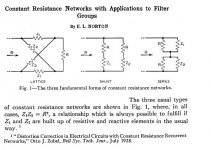
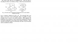
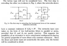
Well, I have been reminding myself what the famous Bell Labs engineer, Edward Lawry Norton, wrote in 1928 or so about Constant Resistance Circuits. He says the series and shunt networks are EQUIVALENT! 
http://www.alcatel-lucent.com/bstj/vol16-1937/articles/bstj16-2-178.pdf
It takes little work to see that if Z1 and Z2 are made into, say 0.33mH and 10uF with R as 8 ohms, you have two topologies that add up to the same result! Series and Parallel filters amount to the SAME THING. No magic sauce here. Game, set and match to ol' Norton here, and an end to the argument, I'd say!
Attachments
you have two topologies that add up to the same result! Series and Parallel filters amount to the SAME THING.
Not quite. The XO point and influence of any point in a series XO affects the entire rest of the XO. In a parallel XO the drivers & their respective network are independent -- one could for instance overlap or spearate XO point for drivers.
This difference can give quite different results.
The last 2 way i was working on, i played & played with parallel, getting closer & closer but not ever happy. At one point i connected the exact same components that represented my best parallel effort to that point in series, and everyting snapped into place. It only took a bit of tweaking from there to end up with a 2 component series XO that works really well.
dave
Ah, there you go again, Dave. You always cling on to the Voodoo Audio explanation. Actually what gives is that parallel networks connected to a particular highish source impedance, say 6 ohms of SET, will interact too.Not quite. The XO point and influence of any point in a series XO affects the entire rest of the XO. In a parallel XO the drivers & their respective network are independent -- one could for instance overlap or spearate XO point for drivers.
This difference can give quite different results.
The last 2 way i was working on, i played & played with parallel, getting closer & closer but not ever happy. At one point i connected the exact same components that represented my best parallel effort to that point in series, and everyting snapped into place. It only took a bit of tweaking from there to end up with a 2 component series XO that works really well.
dave
You really have different design parameters for each network. But I maintain they are analytically equivalent. You can't beat the maths of it.
But FWIW, I think source impedance should get more attention. And series lets you see symmetries that are obscured by a lot of parallel designs. It's also nice that higher order series circuits are less demanding on imperfect inductors too. So both designs should be in your armoury, and deployed when appropriate.
OK, I'm the opposite of a Voodoo Audio guy, but what Dave says makes sense. It's very important to account for the actual driver impedances (not resistors!), and these do interact in a series network in ways they don't in a parallel network. And ditto to your mention of source impedances.
Now, the idea that one topology is intrinsically superior to the other is nonsense. You use the topology that gets you the right transfer function with the fewest number of parts. If memory serves, there were some examples at Rod Elliott's site.
Now, the idea that one topology is intrinsically superior to the other is nonsense. You use the topology that gets you the right transfer function with the fewest number of parts. If memory serves, there were some examples at Rod Elliott's site.
You use the topology that gets you the right transfer function with the fewest number of parts. If memory serves, there were some examples at Rod Elliott's site.
Don't series networks have fewer parts by design, or is that just a trend that I've noticed looking at them?
I remember tinkering with a series crossover once that I managed to get the functions I wanted with around 4 parts, I've just been far too lazy to try and solder it together just yet.
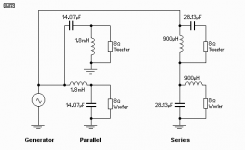
Here's Rod Elliott's simplified second order series design. He would of course correct Le and Re impedance, perhaps even Fs and Qts for the drivers in practise.
http://sound.westhost.com/parallel-series.htm
It's just my intuition, but I'd suspect a series crossover might work particularly well where the tweeter and woofer have much the same inductance. This is doable with, say, small Fostex full-range units which often have a relatively tiny inductance of 0.05mH. This means any Zobel impedance correction networks would be similar in both shunt arms. But then that would apply to parallel networks too.
I quite liked the Norton paper, because it gave you a way to calculate values for third order networks in series crossovers driven by voltage amps, which is otherwise hard.
Attachments
Last edited:
Planet 10 gets it. This is a very complicated time consuming subject. I was fortunate enough to aquire many plans invented by the same designer.
Once you look at enough of these and compare all the diiferent driver parameters and experiment it is not that difficult a concept to understand.
There were many articles in Speaker Builder in the early 80's and AES compialations. .I am not going to reveal trade secrets I have discovered currently being used and might be used again by various people.
There are legal ramifications. Some designs are copyrighted. Not the same as patents. What I do with these for my own personal use is legal. If I want to build these for friends and help other people in their own personal designs I am not infringing on any legal rights. Drivers can be switched by just a few modifications. Most tweeters are croosed over at 2-4khz. Kevlar cones don't perform well with these designs because of the frequency and impedance curvers. You need to use large bandwith drivers because of intermodulation distortion in lower quality drivers.
Listening is subjective and the final test after all the measuring by the various test methods.
I find that all a terrible cop-out, speakerman!
I just don't buy Voodoo audio. It's just plain good or bad engineering in the end and the laws of physics. Series crossovers do allow the drivers to interact via Back EMF. Perhaps even into non-linearity. No coincidence I mentioned Fostex full-range drivers here.
I believe in open-source and sharing of knowledge for the common good. Here's what I know. Class A amps are good. Matching source and load impedance is good in all forms. Cables are cables, just get benign ordinary ones. There's really no difference between a good transistor amp and a valve amp except source impedance which is just a design parameter. Electrolytic capacitors need a polarising voltage to behave linearly. Let's demystify all this Voodoo Audio baloney!
Let's demystify all this Voodoo Audio baloney!
Integrated circuits sound like crap!
*runs away*
- Status
- This old topic is closed. If you want to reopen this topic, contact a moderator using the "Report Post" button.
- Home
- Loudspeakers
- Multi-Way
- Sreten & Speakerman go at series XOs