Hi Guys
Patrick, I feel your pain but would have you look at the two measurements.
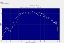
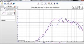
These are the raw responses for a Paraline element driven horn and an SH-50 horn, both driven by the same model driver (The Paraline had wider H, narrower V pattern horn).
These were at different times and places but taken in a more or less same way (TDS) and shown at 1/10 Octave smoothing (although the SH-50 was measured on a tower outdoors at 2meters at twice the Voltage and the Paraline at 1 Meter).
Now, guess which is which? Rather which one has a simpler shape curve to deal with?
A clue, on the white curve, the dip around 4500Hz, is the hf driver radiation exciting the mid drivers low pass filter, as the two driver ranges are coupled together still a little at 4500Hz, shorting the mid drivers terminals (or driving them in use) changes what that feature looks like.
Anyway, when made properly, a Paraline doesn’t need to have big peaks and dips and the Yellow curve for the Paraline response actually has a somewhat simpler shape than the conical. Keep in mind that if one wanted a system with flat response or drooped response with either system, the maximum sensitively is set by the hf end, in this case for Hi Fi say 16KHz or so. Everything below that has to be attenuated to get flat or whatever response shape.
If you have “excessive measurement grass” as opposed to large peaks and dips, see if averaging a number of measurements change the appearance because there are small differences from measurement to measurement. Impulse measurement systems are often limited here and averaging 5 or more sets (like if using ARTA) gives a better (less noisy) measurement.
There are a couple “Things” that come to mind which you need to keep in mind. Make a drawing of what you built, make graph of the cross sectional area each say ¼ inch of progression away from the driver (the pressure waves view more or less). What you don’t want most of all is any portion where the area momentarily reduces and then expands, also not wanted is a portion that doesn’t expand longer than about ¼ inch. Ideally you have a nice expansion.
My first small Paraline prototypes were made from a stack of 5pc of 3/16" metal plates (the first one was plywood, 5 feet tall and the driver 90 degrees off axis to the exit, reminiscent of the old ATT&T microwave horn/reflector towers ).
Before I poured polyurethane into that Paraline on a hunch and sealed up all of the tiny cracks and pores, I was losing a bunch of high end and got a squirrely response at one end of it. These were already clamped together with 12 screws. Oh yeah, let the liquid drain out and then let it sit with a fan blowing on it for a couple days.
Later after that “Duh” moment, sealer was applied on assembly.
Right at the driver exit area of a normal horn, open wood grain can also cost you a few dB at 20KHz.
Lastly, while the easiest to layout and envision, a “line source” is not a desirable shape and has many hidden issues which limit it’s usefulness. While a system which is partially self canceling in the nearfield is a great way to sell a lot of drivers, cabinets and dsp etc, a system which provides the audience with a wide pallet of arrival times given a single input, a frequency response which changes with position and distance and has a limited useful “throw”, does not make for good music or intelligibility.
Even what we call line arrays in concert sound are not, they have a curvature in location, electronically or both making them something like an astigmatic optic or point source who’s origin was different in one plane vs the other.
That (an astigmatic source) is what some of our larger horns (like the J-3, one of my favorites) shown in cut away act like. The big difference is, a horn is not like an array even a continuous line source radiates a frequency dependent interference pattern and radiates a lot more energy outside the pattern to the extent that a single large synergy horn has more pattern control / less energy outside the desired pattern.
If you examine the wave table illustration of a 4 wl source in your post 608, you can see the phase indicated by red and green but also the amplitude in brightness, you can see that source radiates at least 6 fingers and a pattern of lobes and nulls is an interference pattern. If you measure a source with a source size related pattern like this, you see the response in any given location will be different than anywhere else. Once the source is many wavelengths long, the geometry is such that the sound arriving from each portion adds less coherently as you move closer and closer so that the SPL increases more slowly than a point source on axis.
The problem in time (as opposed to the loudness view) is that if you feed a large array like that a single impulsive signal, the ETC and impulse response begins with the arrival of the closest source and the train ends with the arrival from the farthest source, that is to say, not much like the input..
The issue is even a row of drivers radiate as individual sources, even a “true” source can produce an interference pattern and because all of it’s issues are frequency dependent, what you get depends where you are and what frequency.. It’s why things are going so well in the stadium area for us, going up against a big well known line array and smoking it sonically and for less has proven a good sales strategy..
If you want to play with arrays of sources to make directional arrays and such, there is a free program at work you can use. Doug Jones has made a couple how to videos while more for designing installed sound systems, it does cover the how to part. Video’s are here;
DDT training videos | Danley Sound Labs, Inc.
He also did a early blurb using the measured data from a 16 box line array that uses ribbons and the J-1 which has a comparatively small horn above about 300Hz.
http://www.danleysoundlabs.com/danley/wp-content/uploads/2012/01/line-array-paper.pdf
Lastly, there have been suggestions that the synergy horns etc suffer from problems which get worse with increasing levels. Yes, that is true, most of the bad things loudspeakers do involve altering the signal or adding new things and those things get louder faster than the actual signal.
On the other hand, if higher order modes and such were a big problem here, they would be at their worst where these are used, large places at VERY HIGH SPLs using complex horn shapes and the listeners from tens to hundreds even 800 feet away like an end zone football stadium system and using a fraction of the number of drivers and boxes compared to the large line arrays that were removed.. Pop on some headphones;
https://www.dropbox.com/s/tnsw5mb4v5vdlwq/20120726122124.mts
https://www.dropbox.com/s/oyosfc3adc6j1du/20130723135350.mts
Another advantage of not radiating a significant interference pattern is wind has much less of an effect on a point source like this compared to a concert line array in the wind. My daughter and I went on the roof at Tiger Stadium (LSU) in the nose bleed seating area to hear the effect of wind and show how windy it was where the speakers were /sound was traveling..
https://www.dropbox.com/s/dz224imtchuohi4/20130723145400.mts
Anyway, got to run sorry for rambling but for all who celebrate, Merry Christmas to you and yours and hopes 2014 is even better for everyone.
Best,
Tom
For the face book enabled, our Christmas picture with most of us;
https://www.facebook.com/DanleySoundLabs?ref=br_rs
Patrick, I feel your pain but would have you look at the two measurements.
These are the raw responses for a Paraline element driven horn and an SH-50 horn, both driven by the same model driver (The Paraline had wider H, narrower V pattern horn).
These were at different times and places but taken in a more or less same way (TDS) and shown at 1/10 Octave smoothing (although the SH-50 was measured on a tower outdoors at 2meters at twice the Voltage and the Paraline at 1 Meter).
Now, guess which is which? Rather which one has a simpler shape curve to deal with?
A clue, on the white curve, the dip around 4500Hz, is the hf driver radiation exciting the mid drivers low pass filter, as the two driver ranges are coupled together still a little at 4500Hz, shorting the mid drivers terminals (or driving them in use) changes what that feature looks like.
Anyway, when made properly, a Paraline doesn’t need to have big peaks and dips and the Yellow curve for the Paraline response actually has a somewhat simpler shape than the conical. Keep in mind that if one wanted a system with flat response or drooped response with either system, the maximum sensitively is set by the hf end, in this case for Hi Fi say 16KHz or so. Everything below that has to be attenuated to get flat or whatever response shape.
If you have “excessive measurement grass” as opposed to large peaks and dips, see if averaging a number of measurements change the appearance because there are small differences from measurement to measurement. Impulse measurement systems are often limited here and averaging 5 or more sets (like if using ARTA) gives a better (less noisy) measurement.
There are a couple “Things” that come to mind which you need to keep in mind. Make a drawing of what you built, make graph of the cross sectional area each say ¼ inch of progression away from the driver (the pressure waves view more or less). What you don’t want most of all is any portion where the area momentarily reduces and then expands, also not wanted is a portion that doesn’t expand longer than about ¼ inch. Ideally you have a nice expansion.
My first small Paraline prototypes were made from a stack of 5pc of 3/16" metal plates (the first one was plywood, 5 feet tall and the driver 90 degrees off axis to the exit, reminiscent of the old ATT&T microwave horn/reflector towers ).
Before I poured polyurethane into that Paraline on a hunch and sealed up all of the tiny cracks and pores, I was losing a bunch of high end and got a squirrely response at one end of it. These were already clamped together with 12 screws. Oh yeah, let the liquid drain out and then let it sit with a fan blowing on it for a couple days.
Later after that “Duh” moment, sealer was applied on assembly.
Right at the driver exit area of a normal horn, open wood grain can also cost you a few dB at 20KHz.
Lastly, while the easiest to layout and envision, a “line source” is not a desirable shape and has many hidden issues which limit it’s usefulness. While a system which is partially self canceling in the nearfield is a great way to sell a lot of drivers, cabinets and dsp etc, a system which provides the audience with a wide pallet of arrival times given a single input, a frequency response which changes with position and distance and has a limited useful “throw”, does not make for good music or intelligibility.
Even what we call line arrays in concert sound are not, they have a curvature in location, electronically or both making them something like an astigmatic optic or point source who’s origin was different in one plane vs the other.
That (an astigmatic source) is what some of our larger horns (like the J-3, one of my favorites) shown in cut away act like. The big difference is, a horn is not like an array even a continuous line source radiates a frequency dependent interference pattern and radiates a lot more energy outside the pattern to the extent that a single large synergy horn has more pattern control / less energy outside the desired pattern.
If you examine the wave table illustration of a 4 wl source in your post 608, you can see the phase indicated by red and green but also the amplitude in brightness, you can see that source radiates at least 6 fingers and a pattern of lobes and nulls is an interference pattern. If you measure a source with a source size related pattern like this, you see the response in any given location will be different than anywhere else. Once the source is many wavelengths long, the geometry is such that the sound arriving from each portion adds less coherently as you move closer and closer so that the SPL increases more slowly than a point source on axis.
The problem in time (as opposed to the loudness view) is that if you feed a large array like that a single impulsive signal, the ETC and impulse response begins with the arrival of the closest source and the train ends with the arrival from the farthest source, that is to say, not much like the input..
The issue is even a row of drivers radiate as individual sources, even a “true” source can produce an interference pattern and because all of it’s issues are frequency dependent, what you get depends where you are and what frequency.. It’s why things are going so well in the stadium area for us, going up against a big well known line array and smoking it sonically and for less has proven a good sales strategy..
If you want to play with arrays of sources to make directional arrays and such, there is a free program at work you can use. Doug Jones has made a couple how to videos while more for designing installed sound systems, it does cover the how to part. Video’s are here;
DDT training videos | Danley Sound Labs, Inc.
He also did a early blurb using the measured data from a 16 box line array that uses ribbons and the J-1 which has a comparatively small horn above about 300Hz.
http://www.danleysoundlabs.com/danley/wp-content/uploads/2012/01/line-array-paper.pdf
Lastly, there have been suggestions that the synergy horns etc suffer from problems which get worse with increasing levels. Yes, that is true, most of the bad things loudspeakers do involve altering the signal or adding new things and those things get louder faster than the actual signal.
On the other hand, if higher order modes and such were a big problem here, they would be at their worst where these are used, large places at VERY HIGH SPLs using complex horn shapes and the listeners from tens to hundreds even 800 feet away like an end zone football stadium system and using a fraction of the number of drivers and boxes compared to the large line arrays that were removed.. Pop on some headphones;
https://www.dropbox.com/s/tnsw5mb4v5vdlwq/20120726122124.mts
https://www.dropbox.com/s/oyosfc3adc6j1du/20130723135350.mts
Another advantage of not radiating a significant interference pattern is wind has much less of an effect on a point source like this compared to a concert line array in the wind. My daughter and I went on the roof at Tiger Stadium (LSU) in the nose bleed seating area to hear the effect of wind and show how windy it was where the speakers were /sound was traveling..
https://www.dropbox.com/s/dz224imtchuohi4/20130723145400.mts
Anyway, got to run sorry for rambling but for all who celebrate, Merry Christmas to you and yours and hopes 2014 is even better for everyone.
Best,
Tom
For the face book enabled, our Christmas picture with most of us;
https://www.facebook.com/DanleySoundLabs?ref=br_rs
Attachments
John,
Your limited experience has been with extremely poorly made narrow horns, their poor manufacture compounded by putting holes in their throats.
The narrow horn expansion profile you emulated does not have the ragged response you found in your horn.
Unless you test three horns of the same style, differing only in dispersion, your test won't be "an easy way to get some good data".
If you simply take the time to compare frequency response charts of JBL, EV, or any number of manufacturers that make a "family" of horns in different beamwidths, you will find how limited your experience is.
Happy Holidays!
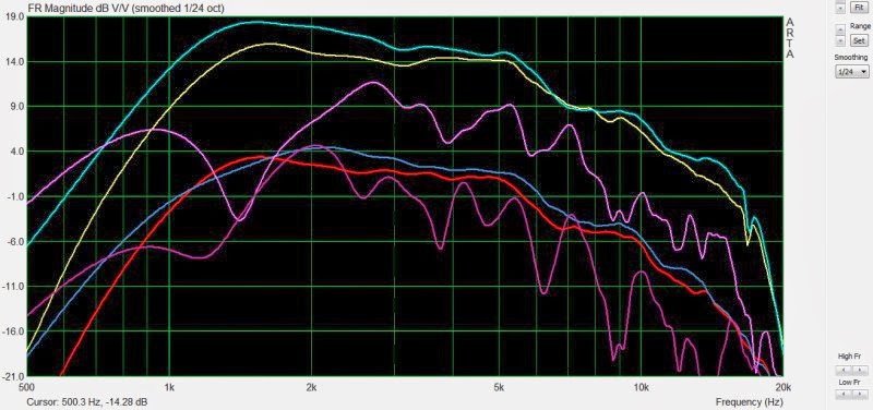
Here's a measurement of two QSC waveguides, and a car audio horn.
The car audio horn is dramatically rougher than the waveguides.
I'd thought this roughness was endemic to *all* narrow angle horns, and had thought that the roughness became worse as the wall angle narrowed.
And when I saw that repeating pattern of peaks and dips, it reminded me of what I was seeing in Paralines, so I drew a connection between the wall angle and the frequency response.
It looks like that is not the case.
Hopefully I don't get flamed for my NEW theory, which is that the roughness in the car audio horn is partially due to a reflection in the throat caused by a 90 degree bend. Along with a lack of termination in the horn.
More data here: http://www.diyaudio.com/forums/multi-way/247744-wide-angle-vs-narrow-angle-horns.html
* kudos to Nate Hansen for providing this measurement of a BMS based Paraline earlier in the thread
The car horn is not really a "narrow angle horn", it is more of an abortive emulation of the old EV 8HD diffraction horn.The car audio horn is dramatically rougher than the waveguides.
I'd thought this roughness was endemic to *all* narrow angle horns, and had thought that the roughness became worse as the wall angle narrowed.
Hopefully I don't get flamed for my NEW theory, which is that the roughness in the car audio horn is partially due to a reflection in the throat caused by a 90 degree bend. Along with a lack of termination in the horn.
The right angle throat reflections and reflections at the bent mouth effectively insure the horn would have a terrible response on any axis of measurement.
Attachments
I'd thought this roughness was endemic to *all* narrow angle horns, and had thought that the roughness became worse as the wall angle narrowed.
There's something strange here, in that you continue plugging away but do not seem to grasp things very well. I'm not sure what it is- this is not meant as an attack, but just an expression of confusion. With thousands of posts on horns, you don't anticipate the garbage horn with a 90 degree kink and no meaningful mouth termination having ****-poor response? Heck, you've measured it before! And the mockups you build with extremely rough walls and whatnot... um what?
Is it a game? If so, you're winning.
Veritas Horn

Image Dynamics Horns
more ID horns

USD horns
See a trend here? "a 90 degree kink and no meaningful mouth termination" indeed. And one of these horns was designed with the help of Bruce Edgar.
This is how it's always been done in car audio. If someone can show me a single car audio horn that doesn't include these features, it's news to me.
That's the entire reason the Paraline was so fascinating to me; the possibility of bending sound without wrecking the impulse response and the frequency response was quite exciting.

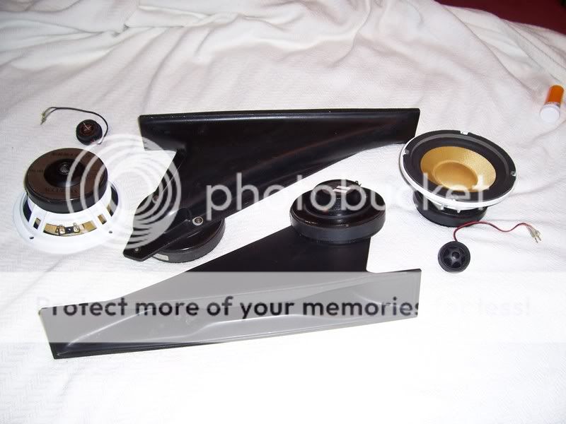
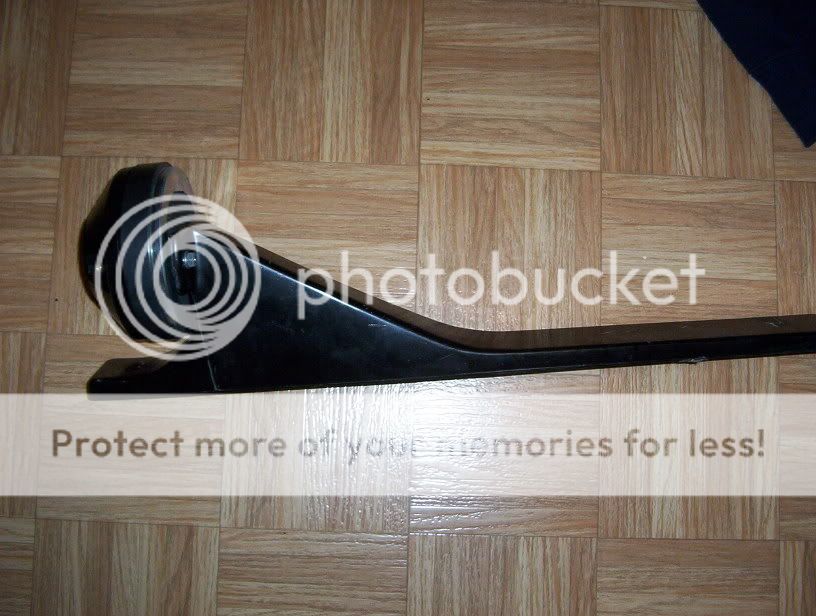
The main reason that I keep beating my head against this problem isn't that I "don't grasp things very well." It's that I don't want to rip out the entire dash of my car to get a 500hz horn in there. That's been the standard solution for most big horns in the car audio arena. The pic above is Mark Eldridges 4Runner, where the entire car is basically built around the horns. (That grey fabric strip that stretches from one side of the windshield to the other is the mouth of Mark's horns.)
Here's an article on one of the many iterations of this car, which details some of the outrageous things that were done to get big dynamics and imaging in a car: http://www.enjoythemusic.com/markeldridge.htm
Last edited:
The trend appears to be badly compromised diffraction horn designs to fit in odd spaces.Veritas Horn
Image Dynamics Horns
more ID horns
USD horns
See a trend here? "a 90 degree kink and no meaningful mouth termination" indeed. And one of these horns was designed with the help of Bruce Edgar.
I remember meeting those guys from Image Dynamic the first time they showed their horns and they were completely clueless about their designs. It appears that others have followed right along with them. And saying that Bruce Edgar had something to do with this just goes to that point in my eyes.
Who in their right mind would aim a high frequency horn at their knees and expect to have good sound, it just defies logic. If this is where automotive high end audio has gone nothing has changed in 20 years.
Who in their right mind would aim a high frequency horn at their knees and expect to have good sound, it just defies logic. If this is where automotive high end audio has gone nothing has changed in 20 years.
The main reason that I keep beating my head against this problem isn't that I "don't grasp things very well." It's that I don't want to rip out the entire dash of my car to get a 500hz horn in there. That's been the standard solution for most big horns in the car audio arena.
First- thanks for taking a little bit of harshness in stride.
In a car, when you can do infinite baffle direct radiators, I don't see the point of an added horn- maybe a waveguide of sorts for coupling with boundaries, but any reasonable install can achieve overwhelming SPL with normal cone 'n dome setups, and no wavefront shaping can be performed in the space available without massive diffraction.
All the shown car horns are junk. That's just how it is. The odd thing is that you would expect any sort of reasonable performance from such a device- you own Summas, I'd think you'd want to try to emulate the smoothness of that type of device, and not have a tolerance for the rough profiles of Q&D assemblies, or highly diffractive profiles.
To be fair, I respect the effort of experimentation- I do some of that myself, but perhaps slowing down a bit might be worthwhile- optimize one thing, until it's performing at a high level, rather than investigating dozens of things at once in haphazard fashion.
I remember meeting those guys from Image Dynamic the first time they showed their horns and they were completely clueless about their designs. It appears that others have followed right along with them. And saying that Bruce Edgar had something to do with this just goes to that point in my eyes.
Who in their right mind would aim a high frequency horn at their knees and expect to have good sound, it just defies logic. If this is where automotive high end audio has gone nothing has changed in 20 years.
Was Edgarhorn and Image Dynamics in the same building, or next door to each other? I know they were close.
In this post*, Edgarhorn is listed 18235 Figueroa St in Gardena CA:
At the Better Business Bureau**, Image Dynamics is listed at the same address.
* Audio Asylum Thread Printer
** Image Dynamics Business Review in Gardena, CA - Serving the Silicon Valley BBB
Both companies have moved on, but it appears that they were close, or possibly even the same office, a few years back. (Not saying that Image Dynamics IS Edgarhorn, just that they were influenced.)
As far as putting horns under the dash - it works surprisingly well!
First off, all loudspeakers sound better when you can't see them. It's the reason that music sounds better with the lights turned off. When you can see where the loudspeakers are, your brain tells you that's where the sound should be coming from.
An externally hosted image should be here but it was not working when we last tested it.
If you look at the dash of a car, the edge is only about eight inches below the 'typical' location for a dome tweeter, which is at the top of the door. And your perception of the loudspeaker isn't where the loudspeaker is; your perception is dictated by the point in the horn where the wavelength can form. IE, when a horn is 2" tall, you don't perceive that the sound is coming from under the dash; you perceive that the sound is the WIDTH of the dash, which is a neat trick. This is because a 2" wavelength is 6,750hz. So the sound is anchored to the dash, not the floor or under the dash.
Unfortunately, massively asymmetrical horns have lots of other issues, which gets back to why the Paraline is fascinating to me.
Last edited:
Patrick,
It was at the CES show in about 1993 or close to that when I met both Edgar and the Image Dynamics guys.
On the horn front in cars I did that in about 1985 in one of my hot rods. There I placed both high frequency and mid horns in the rear deck and used the rear window as a reflector for the sound. I could see doing that in a car if I had the option of designing the sound system and using the front window the same way as a reflector for the highs and mids. The lows could still be in the door or somewhere that you have enough volume for a cone driver.
An ellipse has two focal points inside...
A flat ellipse has 4 potential ports of focused entry or exit...
You could add woofer in the middle somewhere and maybe not
disrupt highs moving through, I mean if the bass tap wasn't in
focus...
Ellipse has a history of another very loud and bright application,
we won't go there...
A flat ellipse has 4 potential ports of focused entry or exit...
You could add woofer in the middle somewhere and maybe not
disrupt highs moving through, I mean if the bass tap wasn't in
focus...
Ellipse has a history of another very loud and bright application,
we won't go there...
Last edited:
Like suppose this ellipse stood in for a plane wave tube.
Except the bass tap can now be hidden from focus.
And because the true impedance in the middle is less
compressed, maybe the taphole leaks less treble too.
Or suppose we put two full range on either side of one
focus and the horn throat at the other...
If you are crazy you could have two horns pointed
opposite ways... Not that you would want to...
Just sayin' it makes an unusual option available
cause the drive is not behind the horn but at the
other focus...
If the horn and CD are on the front face of the ellipse,
the entire back face of the ellipse can be for mids or
woofer. Clearance for much bigger than I drew.
Should the horn throat hole be larger than the CD
hole? To fake like the throat has expanded? Or we
risk turning this to a ring radiator if the throat hole
for the horn is presented that way.
Attachments
Last edited:
So I thought I'd give it a 2'nd try.
About a year ago I tried a 22" tall paraline with two 5.25" PA130 mids and a Dayton compression driver.
It didn't work well at all.
I did it wrong.
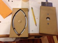
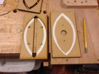
I decided to give it another go. I have access to a laser cutter at work...so I used it to make the fundamental pieces for an 8" paraline.
I used REW for measurements under very non-ideal conditions (sitting on a crowded work bench angled back to avoid that first reflection off the bench). I've still got some early reflections in these measurements and I've smoothed them at 1/24 octave.
Critical points.
1. I used caulk to make 45 degree reflectors at the edges.
2. I used a 45 degree reflector at entry and exit. (These are musts)
3. I braced the center part against the front using small off-cuts. (this one may not be as critical.)
I'm full speed ahead with a full speaker based on these...they turned out pretty good I think.
About a year ago I tried a 22" tall paraline with two 5.25" PA130 mids and a Dayton compression driver.
It didn't work well at all.
I did it wrong.
I decided to give it another go. I have access to a laser cutter at work...so I used it to make the fundamental pieces for an 8" paraline.
I used REW for measurements under very non-ideal conditions (sitting on a crowded work bench angled back to avoid that first reflection off the bench). I've still got some early reflections in these measurements and I've smoothed them at 1/24 octave.
Critical points.
1. I used caulk to make 45 degree reflectors at the edges.
2. I used a 45 degree reflector at entry and exit. (These are musts)
3. I braced the center part against the front using small off-cuts. (this one may not be as critical.)
I'm full speed ahead with a full speaker based on these...they turned out pretty good I think.
Attachments
Mighty nice indeed, material used?
"1/4 inch" MDF...
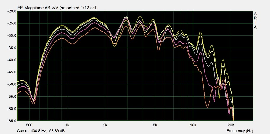
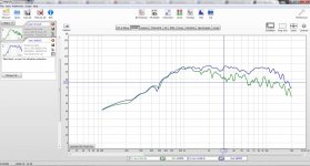
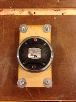
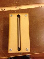
So, I just got in some PRV D280's to try on the paralines...completely different response.
I built two paralines, put a Dayton polyimide driver on one...and a PRV on the other...then swapped paralines/drivers same answer.
Folks more experienced with compression drivers...care to explain the difference?
Both are more than usable in my intended application...it's just the PRV will take a lot more crossover complexity to get there.
Scott
Attachments
So, I just got in some PRV D280's to try on the paralines...completely different response.
I built two paralines, put a Dayton polyimide driver on one...and a PRV on the other...then swapped paralines/drivers same answer.
Folks more experienced with compression drivers...care to explain the difference?
Both are more than usable in my intended application...it's just the PRV will take a lot more crossover complexity to get there.
Scott
An externally hosted image should be here but it was not working when we last tested it.
Horns are resonant devices. If you have two horns of equal length, and one horn is smaller than the other, the peaks in the second horn will be more prominent. You can see this in hornresp; if you make a horn very small it's response becomes very peaky.
One way to combat the peaks in a horn is to increase motor force. For instance, if you take two horns and you power one with a driver that has a BL of 20 it will be less peaky than if you drive the same horn with a driver that has a BL of 10.
This is one of the reasons that prosound drivers often have motors that are more substantial than what you'd find in a driver intended for a sealed box.
If you look at the PRV and the Dayton, the Dayton has a much larger motor. And I think that's why the response of the PRV is peakier.
- Home
- Loudspeakers
- Multi-Way
- Square Pegs