George,
I also am VERY interested in the "spud". I have also been waiting and watching for updates on your web site(for a long time) and forum post (recently). I would sure like to have the resistor and capacitor values to go along with your previous posted schematic. I know you are very busy with work and life. Thanks
Richard
spud schem
I don't believe George would mind..")
But this is the schematic for the version I did up for the AK group.
I believe the only basic difference is George used a slightly lower
plate load for the driver and used an LED to bias it as well.
We've built several this amp with results above our expectations,
I've experimented with the LED's but the simple cathode R is nice.
6LU8 or 6LR8 is the same tube but different socket, the 6MF8 is a
drop in to the circuit as well (6LU8 sub).
Any decently filtered roughly 300v supply will do fine here.
I don't believe George would mind..
But this is the schematic for the version I did up for the AK group.
I believe the only basic difference is George used a slightly lower
plate load for the driver and used an LED to bias it as well.
We've built several this amp with results above our expectations,
I've experimented with the LED's but the simple cathode R is nice.
6LU8 or 6LR8 is the same tube but different socket, the 6MF8 is a
drop in to the circuit as well (6LU8 sub).
Any decently filtered roughly 300v supply will do fine here.
Attachments
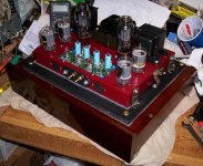
Just for giggles..
Here is a fairly all out version I did up.
I have to say this is one of my favourite amps!
I used an old ST-70 chassis, a left over VTA board and some hammond
organ amp chokes in the supply. (Choke input supply on original ST PT)
This is not push pull, it's paralell Single Ended UL, I used the VTA board
for convenience since it fits the Dynaco chassis (just built my circuit on it)
I stood up the chokes (what looks like outputs in the back) and made some
brackets to mount them, the Edcor outputs are down below, it is LED biased
on the front end with sockets to "roll" LED's.
There is a switch on the board to either use the second triodes in the paralell
6LR8 as a cathode follower to feed those outputs or go straight from the first
triodes plates, it is a combo cathode/fixed bias on the outputs with a smaller R
on the cathode and individual adjustable bias pots on all 4 finals to do the rest.
There's seperate 5v heater transformer down below of 8A, so any rectifiers can
be used of the 5AR4/5U4 pinout, (GZ37 in there now).
This amp has been running for close to a year and it is a nice performer, IMHO..
Attachments
Thanks for the schematic Kegger. Interesting amp. Already gathering the parts to build. I recently built Mikael Abdellah's SE KT88 design (2003). But modified it so it has driver 9 pin sockets for each output tube because I had two 12at7s with a triode section heater burned out and the other triode testing new. Then I thought about wiring each driver in parallel to use lower gain triodes, so I did. Works great. Experimented by comparing a gain circuit to the parallel. The gain circuit had no more gain than the parallel triodes. So with fewer parts the parallel triodes was my choice. I had read about output tubes being parallel for more output power, but not driver tubes. So it is interesting to see your spud amp output parallel and you having switchable choices for the triode sections.
The only spare PT I have now is a 190-0-190. Will the spud amp work at approximately 200V B+ ? Or will I need to buy another power transformer? I have also thought about using a voltage doubler circuit but then I would have over 400 volts.
I have also built tubelabs Simple SE with winter, listening to it right now. Last fall built the Dirt-cheap SET MiniBlok by the late Fred Nachbaur. All great amps. Something about the tube sound that is so appealing and pleasant to the ears.
Richard
Yah you can use a 200v tranny,
I usually do tube rectifiers but do SS as well, with SS rectification and
a cap input your voltage will actually go up, in this case near 250v can
be achieved with a decent size input cap an fairly low resistance choke.
That will give you a decently filtered supply, also if your going the 6LR8
route the roughly 250v supply may make the 6GF7A drop in there to.
Also don't forget to experiment with LED biasing the driver tube, replace
the 620ohm cathode resistor with an LED that has say 1.66-2v of drop.
Now if I were running a 250v supply I'd drop the R5 2.7k resistor to 1K
and make the 100K R6, R8 resistors a single 33K - 47K resistor instead.
Attached is 200v tranny supply I would probably look to run, the choke
would be at least 4H with a DC resistance no greater than 75 ohms so
as not to drop a bunch of unavailable voltage.
(Adjusted current in the supply to account for the less voltage)
P.S. Didn't realize before posting the circuit schematic I'd allready done
so way back on the first page..
Attachments
George, All,
I sure miss going to the Rochester, NY., Hamfest. That one is a 3-1/2 hour drive and I would sleep in my van on the grounds for free in the area by the entrance set up for the purpose. With my health problems and having no spare walking around money it has been probably eight years since I was last able to attend.
Last time I went I scored several older HP BWO microwave lab bench sweep generators, two of which I restored to service and some other microwave gear for my radobs, plus an HP 100 MHz delayed TB dual sweep scope. Another year I scored a very rare 1948 television receiver, now one of the most valuable in my significant collection.
The Canadian Hamfests are not nearly as interesting because all we see show up here is mostly just junk from people's basements and garages. The US Hamfests benefit significantly from the US goverment's large military expenditure, and also from the larger population base and more government and private company laboratories.
Giving this thread a kick...
I have some interest in building a SPUD amp - and if George you would like to post a schematic with values and the layout I would happily put together a PCB - and if there is any interest in a group buy I might be able to swing that too...
Thoughts?
I have some interest in building a SPUD amp - and if George you would like to post a schematic with values and the layout I would happily put together a PCB - and if there is any interest in a group buy I might be able to swing that too...
Thoughts?
kegger said:
But this is the schematic for the version I did up for the AK group.
Just a note: If the 37 V on the cathode of V1_A is correct, approx 1.7 W (P = E^2/R) will be dissipated in the 820 ohm resistor. That's probably fine for a 5 W type at room temperature, but that resistor will get quite hot. I see you recommend using a 10 W type if you substitute a 680 ohm resistor for the 5k||820R combo (I'm guessing those were the values available in your junk box). With 5k||820R, you don't get an even split of the power between the two resistors - the 820R will dissipate the vast majority of it. In the long run, you'd be better off with one 680R resistor.
~Tom
tubelab.com said:I was thinking that the only way it would work was to offer a complete kit, and it would need to be price competitive with some of the other cheap amp kits out there. Once Sherri gets back we may revisit the idea of offering parts kits.
I'd probably bite if there were a competitive kit which included everything but the iron and the chassis. I'm happy enough to source my own transformers, and I don't mind building a chassis out of scrap. Tubes and sockets must be there - passive components don't hurt, but I can order from Mouser if required.
Waay back in the day, I used to buy Heath kits - my first printer was a dot matrix kit, and that thing lasted forever.
But having been in the industry now for too many years to count - a real DIY kit - PCB, comps, tubes, chassis and manuals... thats a big job.
The only way it is feasible to do is if there is an overwhelming market for the amp. George's SPUD only exists in his head at the moment, and like he said before its dwarfed by other requests.
Since the SSE is his biggest seller, that would make the most sense to me to make a kit of it. Even then, there are people that would want everything done for them (OPT's, xfmrs, caps, chassis, tube choice) and there is no complete assy manual for the first time DIY user. Don't get me wrong, he has done a fantastic job for people that understand electrical circuits.
Bottom line is that it doesn't work for a SPUD with *some* interest... (its only 5 watts? that kind of thing)
But - I have no problem taking the design on and making the PCB available ... only of course if George doesn't want to do it himself.
Forgive me if this long and winded, my oldest son graduated from HS today, and I'm feeling old and proud
"Bottom line is that it doesn't work for a SPUD with *some* interest... (its only 5 watts? that kind of thing)"
Hmmmm, could be you are right, and it might not work for tubelab, but this is offered in small batches at an attractive price point. So under some circumstances it appears feasible.
http://www.hawthorneaudio.com/spud_kit.htm
(its only 5 watts? that kind of thing)
Hmmm, seems there is a lot of interest in DIY full range speakers that would run very nicely at that level.
That one is PTP... it actually makes more sense financially to cut out the PCB.
Still a boatload of work.
I've built my own full range horns off of Fostex plans - and they sound fantastic with my SSE. No way would I entertain kitting them for the masses... too many pieces, and I'm barely (in)competent with wood.
Nope, I'll go as far as prototyping a PCB, testing and doing a "George style" web instruction manual. Thats as far as my commitment would go...
Still haven't heard from the man himself - so even that is iffy.
"Only thing is the Hawthorne Online Store reports that the Kit is "Sold Out."
Apparently he is gearing up for another run soon.
http://www.hawthorneaudio.com/forums/viewtopic.php?f=8&t=2962
"That one is PTP... it actually makes more sense financially to cut out the PCB.
Still a boatload of work."
Yes i suspect it would be ton of work, but the parts count is small and the instructions would be minimal for a PCB-the instructions are essentially on the board- with maybe a few pics. Would mostly need the power hook up instructions.
But you are right, only tubelab can decide. Just trying to make the argument that he would have at least one sale <LOL>.
George's SPUD only exists in his head at the moment, and like he said before its dwarfed by other requests.... But you are right, only tubelab can decide. Just trying to make the argument that he would have at least one sale
Board sales have dwindled to 2 or 3 per week in the last few months. The Spud SE will be a small seller, based on emails. The Simple P-P will do much better. There are other boards in the works too.
The Spud board does exist in real life. The first prototype is shown in post #3. There is a second prototype in existence (just minor parts movement to allow easier assembly), and a final version of the layout is ready to go to the PC board house (add solder mask and silkscreen layers). I still plan on getting a small batch made, but the date is up in the air right now. A series of financial setbacks has forced the postponment of all PC board orders including the Simple P-P and the Spud SE. Those two are ready to go.
I started ordering the parts for a "Bag O Parts" kit for The Simple SE, the Simple P-P, and the Spud SE. The Bag O Parts will contain all of the small parts that go on the PC board itself except tubes. It does not make sense for me to supply transformers since there are too many choices, and there would be two shipping charges involved.
The USPS has recently started offering a small parcel flat rate box that ships for the same price as the envelope I use for the boards. This means that I can buy parts from DigiKey, and ship them out with a board for the same shipping charge as the board itself. This is a big deal for people in some countries where shipping costs more than the product.
I have not announced any of this on my web site because I can't commit to a date yet (and it would flood my mailbox). One look at my disorganized web site tells you that I can't possibly keep track of all the parts myself and still have any time left for circuit design. Sherri can do this real easily (and lost her job), but she has been gone for most of this year. When she was here last she set up parts bins, and a spreadsheet, then she had to leave again. She returns in mid July.
The company I work for full time switched health insurance companies at the beginning of the year. The new insurance firm has screwed up every claim that I submitted this year and I didn't even know about it until I returned from up north and found collection notices in the mail. I had to pay almost $4000 out of pocket to avoid collection hassles. I should get that all back when I get the mess fixed. The boards and the remainder of the small parts will be ordered then.
Fair enough then, just print the circuit board and give me a hint where I might buy the sockets.
I am not ready to give up on this yet, but if I do, I will post the artwork files. For those who are in a hurry, the schematic is very similar to the one that Kegger posted. I am sure that his component values will work fine. I will post my schematics with values on my web site when I have gone over everything again. The sockets that I used were made for chassis mount PTP. The pin spacing is sufficient for PCB use, but the 12 pin version isn't. This is why I used the 6LR8 instead of the 6LU8. I have already ordered and received 100 sockets. I got them from Stan at ESRC.
http://www.esrcvacuumtubes.com/
tubelab.com said:
Board sales have dwindled to 2 or 3 per week in the last few months. The Spud SE will be a small seller, based on emails. The Simple P-P will do much better. There are other boards in the works too.
Thats too bad that sales are still down. I really hope things turn around for everyone soon.
The Spud board does exist in real life. The first prototype is shown in post #3. There is a second prototype in existence (just minor parts movement to allow easier assembly), and a final version of the layout is ready to go to the PC board house (add solder mask and silkscreen layers).
Yes I knew that, what I meant was that the component values are still mostly a guess for me - and I'm not comfortable with guessing
I still plan on getting a small batch made, but the date is up in the air right now. A series of financial setbacks has forced the postponment of all PC board orders including the Simple P-P and the Spud SE. Those two are ready to go.
Excellent!
I started ordering the parts for a "Bag O Parts" kit for The Simple SE, the Simple P-P, and the Spud SE. The Bag O Parts will contain all of the small parts that go on the PC board itself except tubes.
Even better!
Personally I don't need to wait for the kit - but I'd be interested in knowing if making it available increases sales for you...
Insurance companies suck. They are right up there with lawyers and politicians...
I am not ready to give up on this yet, but if I do, I will post the artwork files. For those who are in a hurry,
Good enough for me. I was just offering to help, and I certainly don't need the board soon.
- Status
- This old topic is closed. If you want to reopen this topic, contact a moderator using the "Report Post" button.
- Home
- Amplifiers
- Tubes / Valves
- Spud anyone?