Two resistors labeled R1, doh.
To add to the confusion, the schematic printed in the magazine uses different numbers. The feedback resistor is R4.
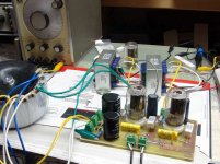
I couldn't wait until next weekend. I put in the 6GF7's and tweaked up the amp. It works best with a lower B+ voltage of 250 volts. At this voltage, with the tube current set so that the tube was running right at the maximum dissipation. Under these conditions the output power varies between 2.5 and 3 watts depending on the tube. I tried about 50 different tubes. Like the 6EM7 there is a large variability in the gain from tube to tube. I replaced the resistor - capacitor combination in the cathode of the driver tube with an LED. This seemed to lower the variability a little.
The sound (and power level) reminds me of a trioded 6V6. It sounds really good, but there is just not quite enough power for my 87db speakers. Slightly more power may be available with a lower impedance OPT, but this usually sacrifices the sound quality.
The power transformer in this photo is an Antek 1T200. I get 249 volts of B+, just right.
Attachments
The first pentode in the 6T10 is intended for operation in a circuit where both G1 and G3 control the flow of current. This is a special type of tube called a dual control pentode. Pete did not need the dual control aspect, so he found the voltage on G3 that resulted in the best linearity.
Ahh!
 Gotcha.
schem
Hey Tubelab,
I'm one of the ones over at AK and doing the 6LU8 project.
I'm with yu and don't put the 6AV5 and 6LU8 pentode in the same stance.
(I've now built both, the 6AV5 is much beefier)
But still no problem running the 6LU8 in UL with a 300V supply, cathode or fixed bias.
I'm also building a paralell version using (2) 6LR8 per channel in SE,UL.
A lot of your testing and torturing of tubes saves me a lot of work, THANK YOU!
Just in case you'd like to see the schem here it is. (simple amp build project)
The amp works pretty darn well, I've had it in quite a few diferent systems as well.
Attachments
tubelab.com said:This particular method of feedback has the advantage of making a pentode look like a triode with almost pentode power output. It usually requires a driver with a relatively high output impedance like a pentode.
The Pentode at the front end acts like a voltage controlled current
source. Able to impose a current onto the plate feedback network,
but not acting as a leak that affects the negative feedback ratio.
You can definately make a driver with less than infinite impedance
work, but it becomes a leaky part of the plate feedback network.
Unpredictable results if that leakage impedance is allowed to vary...
The Cathode resistor below the voltage controlled current source
should not be bypassed with a cap, as the Pentode by itself is not
able to produce a sufficiently linear ratio of current.
Bypass the heck out of the output pentode's cathode, its got all
the Schade NFB it needs already.
You can see the N and P Fetrons doing exactly the same thing,
with only slightly different bias arrangement. jFET drains are tied
high up in the dividers to insure they DO NOT operate in the triode
region. Oddly enough, the lack of a high pentode like impedance
here at this first drain would make the emulator far less Triodish...
These spuds seem to be doing almost exactly the same thing.
Making one really great Triode out of two ordinary Pentodes...
All three emulated triodes (inlcuding the Spud) are a bit wierd in
this simplified topology, they are non-inverting...
Attachments
Kegger:
Our schematics are very similar considering independent development. Differences are:
I chose the 6LR8 over the 6LU8 because the 6LR8 and the 6GF7 (a dual dissimilar triode also made for TV vertical sweep) share the same pinout (except the screen grid is an NC on the triode). This allows two amps in one design. There may be a similar twin for the 6LU8 but I haven't found it.
I don't use the decoupling network on the driver (C2, C5, R5) it is often not needed on a two stage amp. It certainly won't hurt, and is generally a "proper" thing to do.
Every resistor is a slightly different value, but I am still tweaking. The big difference is R2. It can be considerably higher. The book says 1 to 2.2 meg is OK in cathode bias. I don't go that high to avoid grid current issues in old tubes. I have 470K. This gives a little more gain. R11 is also 470K, but this is just because I am already using 470K.
I am running both stages at a higher current. I have a 680 ohm cathode resistor (R1, R7) and R12 is 150 ohm. The tube operates over spec, but this is my style. I have already reduced the current in an attempt to find a set of values that work with both tubes.
I am also running the first stage at a higher current. I have an LED in place of R4, and the plate load (R6,R8) is 22K. The feedback resistor (R3) is 150K. This works out to about the same feedback ratio. I may lower the current some because the gain is good with the 6LR8, but a little low with the 6GF7.
I am currently experimenting with the 6GF7 design. I think I like the sound better despite the lower power. I will flip flop back and forth until I find a set of components that work for both designs, or convince myself that it can't be done. The big disconnect is the supply voltage. The 6LR8 likes 300 to 350 volts, and the 6GF7 is most happy at 250 volts.
I have a 21LR8 with a crack in the glass. The crack has grown longer (it is about 1.5 inches long now) as I have been using the tube. I guess I will "test" it before it sucks air by itself.
Our schematics are very similar considering independent development. Differences are:
I chose the 6LR8 over the 6LU8 because the 6LR8 and the 6GF7 (a dual dissimilar triode also made for TV vertical sweep) share the same pinout (except the screen grid is an NC on the triode). This allows two amps in one design. There may be a similar twin for the 6LU8 but I haven't found it.
I don't use the decoupling network on the driver (C2, C5, R5) it is often not needed on a two stage amp. It certainly won't hurt, and is generally a "proper" thing to do.
Every resistor is a slightly different value, but I am still tweaking. The big difference is R2. It can be considerably higher. The book says 1 to 2.2 meg is OK in cathode bias. I don't go that high to avoid grid current issues in old tubes. I have 470K. This gives a little more gain. R11 is also 470K, but this is just because I am already using 470K.
I am running both stages at a higher current. I have a 680 ohm cathode resistor (R1, R7) and R12 is 150 ohm. The tube operates over spec, but this is my style. I have already reduced the current in an attempt to find a set of values that work with both tubes.
I am also running the first stage at a higher current. I have an LED in place of R4, and the plate load (R6,R8) is 22K. The feedback resistor (R3) is 150K. This works out to about the same feedback ratio. I may lower the current some because the gain is good with the 6LR8, but a little low with the 6GF7.
I am currently experimenting with the 6GF7 design. I think I like the sound better despite the lower power. I will flip flop back and forth until I find a set of components that work for both designs, or convince myself that it can't be done. The big disconnect is the supply voltage. The 6LR8 likes 300 to 350 volts, and the 6GF7 is most happy at 250 volts.
A lot of your testing and torturing of tubes saves me a lot of work, THANK YOU!
I have a 21LR8 with a crack in the glass. The crack has grown longer (it is about 1.5 inches long now) as I have been using the tube. I guess I will "test" it before it sucks air by itself.
design
Tubelab
Thanks for the rundown on the schems.
I to made my choice of 6LU8 over the 6LR8 (this project) for tube swapping.")
As the 6MF8 drops right in as well, I've tested them and there right at home.
(the current drops a bit on the 6MF8 and puts it right in line with dissipation)
There's the bigger guy the 6MY8 but I only have 1, then the 6JZ8, but it like
the 6GF7 wants less voltage as well so I counted it out for this simple build.
Were actually pretty much the same pentode cathode resistor as my pair is
705 ohms (or sub 1 for 680ohm) so I think we got the pentode where we like.
I went with R12 being 1.2k to make sure of no oscilation and it just happens
to drop voltage enough to where the plate and screen see the same in UL.
Also I chose both grid resistors to be the same as yah I was using the 270K
on the driver so I used it on the pentode as well, I saw those high numbers in
the (PDF) but again chose the lower value for suspect tubes or different tubes.
(got plenty of gain with using 270K, that is for the 6LU8 and 6MF8)
We are a bit different on the front tube, I went with my general rule of trying to
be 4x to 5x the plate resistance of the tube for my plate load while still getting
decent current and voltage on the tube. I shot for the most current I could get
in choosing my cathode resistor while having roughly 2v bias on that tube to.
(My thinking was I wanted to be within 1.5v - 2v bias and have it drive well)
Experimented with different amounts of feedback and settled on the current in
a realization that more didn't do to much for technical performance but did in a
sound performance, I think I found a happy medium.
I was considering experimenting with LED bias for my own version, but with the
50K plate load, biasing on the driver and the 270K feedback resistor gain works
out to be very nice and the sound is quite good for this quite simple amp project.
I will be very interested in your final schem choices, ecspecially the driver section.
What a weird world it is we choose to build such simular amps at the same time,
I'm glad to see someone such as yourself designing/creating this spudly compact.
I have found the sound of the 6LU8/6MF8 better in UL Than in Triode.
(At least on the EDCOR tranny, technical performance improves as well, so)
Hope your tubes don't Crack under the pressure before your done,
Please keep the updates coming, I'm always up for reading more of your experiments.
Tubelab
Thanks for the rundown on the schems.
I to made my choice of 6LU8 over the 6LR8 (this project) for tube swapping.
As the 6MF8 drops right in as well, I've tested them and there right at home.
(the current drops a bit on the 6MF8 and puts it right in line with dissipation)
There's the bigger guy the 6MY8 but I only have 1, then the 6JZ8, but it like
the 6GF7 wants less voltage as well so I counted it out for this simple build.
Were actually pretty much the same pentode cathode resistor as my pair is
705 ohms (or sub 1 for 680ohm) so I think we got the pentode where we like.
I went with R12 being 1.2k to make sure of no oscilation and it just happens
to drop voltage enough to where the plate and screen see the same in UL.
Also I chose both grid resistors to be the same as yah I was using the 270K
on the driver so I used it on the pentode as well, I saw those high numbers in
the (PDF) but again chose the lower value for suspect tubes or different tubes.
(got plenty of gain with using 270K, that is for the 6LU8 and 6MF8)
We are a bit different on the front tube, I went with my general rule of trying to
be 4x to 5x the plate resistance of the tube for my plate load while still getting
decent current and voltage on the tube. I shot for the most current I could get
in choosing my cathode resistor while having roughly 2v bias on that tube to.
(My thinking was I wanted to be within 1.5v - 2v bias and have it drive well)
Experimented with different amounts of feedback and settled on the current in
a realization that more didn't do to much for technical performance but did in a
sound performance, I think I found a happy medium.
I was considering experimenting with LED bias for my own version, but with the
50K plate load, biasing on the driver and the 270K feedback resistor gain works
out to be very nice and the sound is quite good for this quite simple amp project.
I will be very interested in your final schem choices, ecspecially the driver section.
What a weird world it is we choose to build such simular amps at the same time,
I'm glad to see someone such as yourself designing/creating this spudly compact.
I have found the sound of the 6LU8/6MF8 better in UL Than in Triode.
(At least on the EDCOR tranny, technical performance improves as well, so)
Hope your tubes don't Crack under the pressure before your done,
Please keep the updates coming, I'm always up for reading more of your experiments.
Re: design
Have you tried Pentode mode? With your plate-to-plate Schade
style Triode emulation, UL or Triode strapping the screen seems
a redundant excercise. And reduces plate performance as noted...
Or does the screen dissipation drive favorably into the UL Tap?
With beam pentodes, the screen is not supossedly in the direct
conducting path of the beams, the plate is the business end...
Reality might be a bit more fuzzy.
kegger said:I have found the sound of the 6LU8/6MF8 better in UL Than in Triode.
(At least on the EDCOR tranny, technical performance improves as well, so)
Have you tried Pentode mode? With your plate-to-plate Schade
style Triode emulation, UL or Triode strapping the screen seems
a redundant excercise. And reduces plate performance as noted...
Or does the screen dissipation drive favorably into the UL Tap?
With beam pentodes, the screen is not supossedly in the direct
conducting path of the beams, the plate is the business end...
Reality might be a bit more fuzzy.
Pentode
Yes and no, I did just a resistive voltage dropper for the screen and not
a nice low impeadance regulated screen supply, performance was better
both in sound and on the spec sheet in UL/Triode.
I also ran the amp in UL/Triode without the plate to plate/grid feedback an
got better specs with the feedback plus the amp digs a bit deeper an has
a more extended top end or you could just say the amp is flatter.
This was a simple project and wanting to keep it that way a regulated G2
supply wasn't something I felt was warrented to try since we had UL taps.
Again the goal was a simple, easy amp to build and perform fairly well.
I'm sure more could be done with the setup and some more engineering.
Overall the amp responds pretty darn well for the criteria.
I'm pleased with it, for now. (down the road, well who knows)
We are a bit different on the front tube, I went with my general rule of trying to be 4x to 5x the plate resistance of the tube
In reality my 22K value comes from what was left in the Simple SE board from a previous experiment. The "furball" was built on a Simple SE board that has been used for dozens of experiments. it has been converted to P-P and back to SE, and it still worked. It was last used with E130L tubes in SE mode. I think that the 22K was left over from use as a phase splitter. I just blindly copied those values into the spud board. Some more tweaking will occur, especially with the 6GF7.
There's the bigger guy the 6MY8 but I only have 1, then the 6JZ8
I have some 6JZ8's and some 17JZ8's but I didn't realize that they have the same pinout as the 6LU8. They are on my list of tubes to "test". I remembered the 6LU8 and the 6JZ8 from my days in the TV repair business (1969 - 1971). I have never heard of the 6MY8, and I don't have any. They aren't in any of my books, and not listed at Franks.
Have you tried Pentode mode?
I tried pentode mode early on in the "furball" experiment and wasn't too impressed. That may have been before I got the plate to plate feedback optimized. It seemed that pentode mode offered very little power improvement over UL but cost some output impedance. I will try it again next time I put the pentodes back in. Iv'e got 6GF7's in there now.
I have found the sound of the 6LU8/6MF8 better in UL Than in Triode.
It definitely has more dynamics in UL with the little Edcor. I think that triode sounded slightly better with the big Edcors. I haven't done too much measurements yet.
Hope your tubes don't Crack under the pressure before your done
I have one that is cracked from mishandling. I guess that I am going to "test" it while it still has some vacuum.

With a PCB, you could use a circle of Mill-Max single-pin sockets and avoid having to find NOS PCB sockets...
Who needs NOS when we have Chinese! The Chinese are now making new production 9 and 12 pin ceramic Compactron sockets. They are intended for chassis mount, but they can be used in a PC board. They are used in my board.
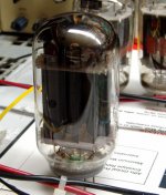
OK, you asked for it. I have a 21LR8 with a crack down the side. It is a Silvertone (Sears) branded tube. It is made in Japan. It does work, and doesn't exhibit signs of "gas". I used this one during the initial test and development of this amp. It looks like the crack has grown since I started using it.
These tubes were stored in boxes, exposed to the elements in Florida for several years and dumped into bins. They were loose tubes, not in their original boxes. Many were broken and new tubes were mixed in with used and broken tubes, but I got them for free.
I have learned that cracked tubes like these are unstable. They can shatter when they get hot. I have an 833A with a similar crack. I am afraid to crank that one up. Likewise, I would be hesitant to rely on this one, so its test time. Lets see what these things can do.
Attachments
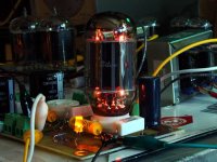
I have already been up to 400 volts of B+ in UL mode with these tubes, so I will start here. This puts about 355 volts across the tube. Power output is 8.5 watts at 5% distortion. The tube is not even getting excited, no glow on plate or screen. Tube dissipation is about 16 watts.
Attachments
Next stop 450 volts of B+. 390 volts across the tube. This is max rated plate voltage, 100 volts above max rated screen voltage. Tube dissipation is 21 watts. I let it sit at this level for 10 minutes. It did not shatter, and there was no sign of runaway or gasseous glow. In fact there was NO glow on plate or screen. Power output is 10 watts at 5% distortion.
I rotated the PC board to show the side of the plate that does glow when you really crank it.
I rotated the PC board to show the side of the plate that does glow when you really crank it.
Attachments
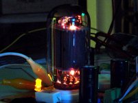
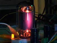
OK, I set the power supply for 500 volts! This puts 435 volts across the tube. The cathode current is now 93 mA. Power output is 12 watts at 5% distortion. This is a tube dissipation of about 28 watts (435 volts * .093 = 40 watts - 12 watts delivered to the load). There is some glow visible on the center of one side of the plate. There is NO glow visible on the screen grid, but there is some blue glow inside around the grids. This is to be expected at TWICE the normal rated dissipation. I let it run for about 5 minutes at this level. There were no unexpected events.
The cathode resistor is now dissipating 5.9 watts, it is a 5 watt resistor and I have had these fail before resulting in an exploded bypass cap. It makes a mess out of the PC board and stinks up the whole house.
My camera responds to infared so the glow in the picture is worse than that seen with the eyes in a dark room.
Attachments
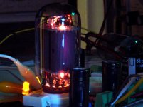
OK, time for worse case. Same conditions as before, but I turned down the audio generator so that the output power was now 0.1 watt instead of 12+ watts. Now the tube gets to eat all 40 watts that it is fed. No signal is always worst case dissipation in a class A amp. The photo is after about 2 minutes. I shut it off because things were getting really HOT!
What does all of this mean? First off, it means that you don't have to worry about blasting the screen grid in UL, or if you slightly exceed the 300 volt rating. It also means that the 14 watt plate dissipation rating is at least conservative. I would have no problem running these tubes at 14 watts, maybe a little more.
NOTE, this is a sample size of ONE, and it is a Japanese tube. I may repeat some testing on some USA made samples that I have, but I won't glow them as hard.
Attachments
- Status
- This old topic is closed. If you want to reopen this topic, contact a moderator using the "Report Post" button.
- Home
- Amplifiers
- Tubes / Valves
- Spud anyone?