Is this last "Office 2000" the MS product?
Yes.
I think the parallax might be to blame
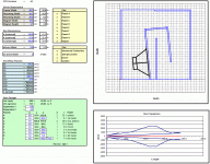
I've enclosed a file anyway if you want to take a look. The production version is a little, but not significantly, tweaked, but that's on the laptop and not handy.
I know I'll need a a few angled blocks to pad out some of the corners, but the rebates are just for the structural stuff.
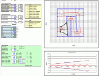
Interesting approach you took there with expanding the thickness of panel #5 in order to address the horn expansion around that particular area. Overall though it looks pretty decent, though I might have tried a slightly different initial expansion angle to minimize the errors a bit.
Do you have any way of measuring the TH after you've built it? I'd be particularly interested in an impedance curve, for example.
Good luck with your build!
I think I changed the start angle in the final sim. I'm also going to play with moving the mouth anticlockwise so it fires to the left. I've hand calculated the path difference and simmed it in HR and it seems to work, but measurement will reveal all. 
Expanding panel #5 also gives me room to add a Class D amp module, as this will be a self powered solution for a small PA system I'm building. I'll post the HR graph next time I have the laptop fired up.
I'll post more pics and curves once I get to that stage.
Expanding panel #5 also gives me room to add a Class D amp module, as this will be a self powered solution for a small PA system I'm building. I'll post the HR graph next time I have the laptop fired up.
I'll post more pics and curves once I get to that stage.
Hi Brian,
first of all let me say your spreadsheets are great!!! Thank you for this fantastic tool!!
Before the existence of your spreadsheets I had to waste really a lot of time trying to fold my tapped horn projects using autocad but trying to find the right point for folds across the path length was really a problem.
Tham layout is my favorite one because 99% of the panels have 90degree cuts.
Have you ever considered to create a spreadsheet for this layout??

I like this design because it is possible to build it and test it with different mouths using different front panels.
Also the possibility to specify a different thickness for baffle panel would allow me to specify a baffle made with two panels
This will make it possible to design a removable baffle and have the possibility to test the horn with driver hole in different points of the baffle.
Please let me know if it is possible to create such spreadsheet because I am absolutely not able to do reverse engineering on existing sheets.
Thank you in advance for your attention
Massimiliano
first of all let me say your spreadsheets are great!!! Thank you for this fantastic tool!!
Before the existence of your spreadsheets I had to waste really a lot of time trying to fold my tapped horn projects using autocad but trying to find the right point for folds across the path length was really a problem.
Tham layout is my favorite one because 99% of the panels have 90degree cuts.
Have you ever considered to create a spreadsheet for this layout??

I like this design because it is possible to build it and test it with different mouths using different front panels.
Also the possibility to specify a different thickness for baffle panel would allow me to specify a baffle made with two panels
This will make it possible to design a removable baffle and have the possibility to test the horn with driver hole in different points of the baffle.
Please let me know if it is possible to create such spreadsheet because I am absolutely not able to do reverse engineering on existing sheets.
Thank you in advance for your attention
Massimiliano
That's the fold I prefer too!
It usually takes me a few days to put together a folding spreadsheet for a new fold and work out all the bugs. I'll have a look at it when I get some more free time.
I love that refold of William Cowan's 30Hz horn but which driver is it for? Eminence has two different Definimax 12's, the 4012ULF and the 4012HO. I presume only one of these would work best. Also wondering if the same enclosure could work with other 12's like Peerless 835017 XXLS or the much cheaper Peerless 830669 SLS.
It usually takes me a few days to put together a folding spreadsheet for a new fold and work out all the bugs. I'll have a look at it when I get some more free time.
Awesome, I like those folds too, super easy to build.
It usually takes me a few days to put together a folding spreadsheet for a new fold and work out all the bugs. I'll have a look at it when I get some more free time.
Wow! This is great!!
Thank you so much Brian.


I will try different driver positions and different mouths (even crazy ones like the 7th flute style mouth
I just need proper bracing for the removable panels.
An externally hosted image should be here but it was not working when we last tested it.
Last edited:
Wow! This is great!!
Thank you so much Brian.


Looks like I might be able to finish this up a lot faster than I thought. I've already got most of the layout down. Once that's done, putting in the sample points should be easy enough, as the technique is a simple one. This should be done by tomorrow, if nothing else ends up taking up my time.
Attachments
You are a gentleman and a scholarLooks like I might be able to finish this up a lot faster than I thought. I've already got most of the layout down. Once that's done, putting in the sample points should be easy enough, as the technique is a simple one. This should be done by tomorrow, if nothing else ends up taking up my time.
Looks like I might be able to finish this up a lot faster than I thought. I've already got most of the layout down. Once that's done, putting in the sample points should be easy enough, as the technique is a simple one. This should be done by tomorrow, if nothing else ends up taking up my time.
This is me after your post..


An externally hosted image should be here but it was not working when we last tested it.
Looks like I might be able to finish this up a lot faster than I thought. I've already got most of the layout down. Once that's done, putting in the sample points should be easy enough, as the technique is a simple one. This should be done by tomorrow, if nothing else ends up taking up my time.
...and here we go, v1.0.
Expect a few bugs of course
This one assumes constant expansion throughout. I'm going to redo it to reflect a dual expansion with the second occurring on the last bend before the mouth, which should allow simming of different mouth sizes.
I've run into a problem trying to programmatically determine L34 (or soon to be L45). For the moment I've set it to L12 + panel thickness (like if the horn's mouth is at the bottom rather than the front. This means that it might be off a few inches compared to the sim.
Attachments
...and here we go, v1.0.
Expect a few bugs of course
This one assumes constant expansion throughout. I'm going to redo it to reflect a dual expansion with the second occurring on the last bend before the mouth, which should allow simming of different mouth sizes.
I've run into a problem trying to programmatically determine L34 (or soon to be L45). For the moment I've set it to L12 + panel thickness (like if the horn's mouth is at the bottom rather than the front. This means that it might be off a few inches compared to the sim.
Brian,
I'm totally speechless and infinitely grateful!!
I will play with it as soon as I come back home.
Thank you so much!!!
Does this mean the mouth shown on the left side is not what is calculated?...and here we go, v1.0............ For the moment I've set it to L12 + panel thickness (like if the horn's mouth is at the bottom rather than the front. ...............
Is the mouth actually in the bottom face?
Does this mean the mouth shown on the left side is not what is calculated?
Is the mouth actually in the bottom face?
Nope, the mouth is to the side. The estimated HornResp parameters would be a lot more accurate if the mouth was at the bottom though. Maybe I should do a version that reflects that
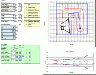
With the mouth on the side, not only is there an issue with accurately estimating L34 (or L34 and L45 in the new version attached), I think that there is a large amount of error introduced in trying to estimate the effective mouth size too. This is all a by-product of trying to put together a sim that has a large bend right at the mouth. The big bump in the "horn expansion graph" right at the end is a visual indicator of what's going on.
In summary I'd trust the estimated HornResp parameters up to S3 in the new version attached. The rest may need to be worked out by trial and error, unless someone has a better way of estimating the path length and cross-sectional area through the section in question.
Note: this new version treats the horn as dual expansion, to allow for different mouth sizes for the same fold. It does mean however that the driver's center cannot be moved up higher than the top edge of the mouth, which is considered to be the location of S3. This does introduce some limitations to the driver's location in the horn, but nothing to serious I think.
My suggestion would be that if anyone's planning to build something based on a model from this spreadsheet, make the front panel removable, and use FR and impedance measurements to determine the best mouth size, shape and location. And it seems that at least one person is thinking of doing that already
Attachments
- Home
- Loudspeakers
- Subwoofers
- Spreadsheet for Folded Horn Layouts...


