Re: Open loop measure
I'm not sure what that second sentence means, Rafael. Could you rephrase it?
Simulate with the actual load you're going to use. You can see, for example, how capacitive loads affect stability by doing this.
When I do a loop gain simulation, I usually open up LoopGain2.asc and copy the Ii and Vi sources using F6, then paste into my schematic using Ctrl-V. This changes the reference numbers of Ii and Vi to something like Ii1 and Vi1, so I change the names back to the original Ii and Vi. This is because the loop gain formula refers specifically to Ii and Vi. From LoopGain2.asc, I copy the formula for loop gain and save it as a comment in my .asc file. Then when I need to plot it, I just paste the comment into the expression box of the waveform viewer.
Rafael.luc said:I am using method Middlebrook to simulate ( LoopGain2.asc in LTspice).
By this method I have to set the in open loop, gain= 1(RF1=1K and RF2=1K), I am sure ?
I'm not sure what that second sentence means, Rafael. Could you rephrase it?
Measure open loop is with load or without load?
Simulate with the actual load you're going to use. You can see, for example, how capacitive loads affect stability by doing this.
When I do a loop gain simulation, I usually open up LoopGain2.asc and copy the Ii and Vi sources using F6, then paste into my schematic using Ctrl-V. This changes the reference numbers of Ii and Vi to something like Ii1 and Vi1, so I change the names back to the original Ii and Vi. This is because the loop gain formula refers specifically to Ii and Vi. From LoopGain2.asc, I copy the formula for loop gain and save it as a comment in my .asc file. Then when I need to plot it, I just paste the comment into the expression box of the waveform viewer.
Re: Re: Open loop measure
Sorry I not explained correctly
I rename the two resistors responsible for the gain in feedback-link to "RF1" and "RF2", as in the diagram below:
http://www.ecircuitcenter.com/Circuits_Audio_Amp/Basic_Amplifier/Basic_Audio_Amplifier.htm
I want to know, is to define the open loop gain for the simulation (method LoopGain2.asc )
I leave it to closed loop gain(Ex: Gain =30dB)?
Or set the gain as 1?
In the figure below, the simulation with closed loop (11dB gain in closed loop )
andy_c said:
I'm not sure what that second sentence means, Rafael. Could you rephrase it?
Sorry I not explained correctly
I rename the two resistors responsible for the gain in feedback-link to "RF1" and "RF2", as in the diagram below:
http://www.ecircuitcenter.com/Circuits_Audio_Amp/Basic_Amplifier/Basic_Audio_Amplifier.htm
I want to know, is to define the open loop gain for the simulation (method LoopGain2.asc )
I leave it to closed loop gain(Ex: Gain =30dB)?
Or set the gain as 1?
I think not have problems to implement method.andy_c said:
Simulate with the actual load you're going to use. You can see, for example, how capacitive loads affect stability by doing this.
When I do a loop gain simulation, I usually open up LoopGain2.asc and copy the Ii and Vi sources using F6, then paste into my schematic using Ctrl-V. This changes the reference numbers of Ii and Vi to something like Ii1 and Vi1, so I change the names back to the original Ii and Vi. This is because the loop gain formula refers specifically to Ii and Vi. From LoopGain2.asc, I copy the formula for loop gain and save it as a comment in my .asc file. Then when I need to plot it, I just paste the comment into the expression box of the waveform viewer.
In the figure below, the simulation with closed loop (11dB gain in closed loop )
Attachments


Hi Rafael,
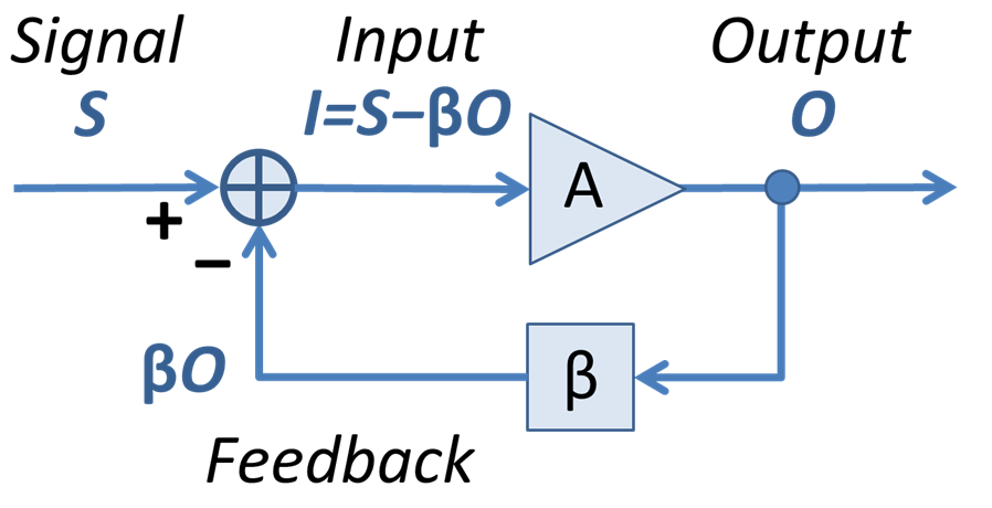
I think this is an issue of terminology. Just so we're talking about the same thing, have a look at figure 1 on this page, also shown below.
 .
.
The "open-loop gain" is AOL in the picture. But that's not the quantity simulated by the Middlebrook probe in the LoopGain2.asc. The probe in LoopGain2.asc measures the "loop gain". In the figure above, the loop gain is AOL * beta. That's all the way around the loop, neglecting the minus sign. In your simulations above, you did them with two different values of beta (the resistor divider ratio), so you end up with two different values of loop gain. Each is correct for the particular circuit being simulated.
Let's say you wanted to actually simulate the open-loop gain AOL. You might want to do this to compare what SPICE says to the op-amp datasheet plot of AOL. To do that, you don't need the Middlebrook loop gain probe at all. The easiest way is to label the op-amp non-inverting input node as, say, "a", its inverting input node as, say, "b", and its output node as, say, "out". Then just apply an AC input signal and plot V(out)/(V(a)-V(b)).
The reason for plotting the loop gain is as follows. If we compute V(output) / V(input) in the figure above, we get:
Vout/Vin = AOL/(1 + AOLB)
I've used "B" for "beta" above. If the magnitude of AOLB is 1 where its phase is -180 deg, that's the same as AOLB = -1. That would make the denominator of the right hand side of the equation above zero, giving infinite gain, which is the same as having an oscillator.
I think this is an issue of terminology. Just so we're talking about the same thing, have a look at figure 1 on this page, also shown below.
The "open-loop gain" is AOL in the picture. But that's not the quantity simulated by the Middlebrook probe in the LoopGain2.asc. The probe in LoopGain2.asc measures the "loop gain". In the figure above, the loop gain is AOL * beta. That's all the way around the loop, neglecting the minus sign. In your simulations above, you did them with two different values of beta (the resistor divider ratio), so you end up with two different values of loop gain. Each is correct for the particular circuit being simulated.
Let's say you wanted to actually simulate the open-loop gain AOL. You might want to do this to compare what SPICE says to the op-amp datasheet plot of AOL. To do that, you don't need the Middlebrook loop gain probe at all. The easiest way is to label the op-amp non-inverting input node as, say, "a", its inverting input node as, say, "b", and its output node as, say, "out". Then just apply an AC input signal and plot V(out)/(V(a)-V(b)).
The reason for plotting the loop gain is as follows. If we compute V(output) / V(input) in the figure above, we get:
Vout/Vin = AOL/(1 + AOLB)
I've used "B" for "beta" above. If the magnitude of AOLB is 1 where its phase is -180 deg, that's the same as AOLB = -1. That would make the denominator of the right hand side of the equation above zero, giving infinite gain, which is the same as having an oscillator.
Hi Andy
With this method, is correct for to determine the phase margin, to the circuit does not oscillate (I use Bode)
Simulate a simple amp in AC analysis (set AC=1)
Gain closed loop: 20dB, 1.2Mhz -3dB
Gain open loop: 84dB, 980Hz -3dB
Middlebrook : 42dB, 5Khz -3dB 😕
phase at 0dB, 90 degrees in all
Attached two circuits simple amp, AOL and Middlebrook (LTspice)
Thanks
Ok, worked 😀andy_c said:Let's say you wanted to actually simulate the open-loop gain AOL. You might want to do this to compare what SPICE says to the op-amp datasheet plot of AOL. To do that, you don't need the Middlebrook loop gain probe at all. The easiest way is to label the op-amp non-inverting input node as, say, "a", its inverting input node as, say, "b", and its output node as, say, "out". Then just apply an AC input signal and plot V(out)/(V(a)-V(b)).
With this method, is correct for to determine the phase margin, to the circuit does not oscillate (I use Bode)
Not understand! What is the simulation Middlebrook probe, what I am simulating 😕andy_c said:The "open-loop gain" is AOL in the picture. But that's not the quantity simulated by the Middlebrook probe in the LoopGain2.asc. The probe in LoopGain2.asc measures the "loop gain".
Simulate a simple amp in AC analysis (set AC=1)
Gain closed loop: 20dB, 1.2Mhz -3dB
Gain open loop: 84dB, 980Hz -3dB
Middlebrook : 42dB, 5Khz -3dB 😕
phase at 0dB, 90 degrees in all
You explained, the Mathematical of simulation or I need to apply any expression?andy_c said:The reason for plotting the loop gain is as follows. If we compute V(output) / V(input) in the figure above, we get:
Vout/Vin = AOL/(1 + AOLB)
I've used "B" for "beta" above. If the magnitude of AOLB is 1 where its phase is -180 deg, that's the same as AOLB = -1. That would make the denominator of the right hand side of the equation above zero, giving infinite gain, which is the same as having an oscillator.
Attached two circuits simple amp, AOL and Middlebrook (LTspice)
Thanks
Attachments
Rafael.luc said:Ok, worked 😀
With this method, is correct for to determine the phase margin, to the circuit does not oscillate (I use Bode)
Ok, now you have computed AOL, the open-loop gain of just the op-amp itself. If you try this with an IC op-amp, you can compare the data with the op-amp's data sheet plot of AOL vs. frequency. They should look very similar.
But it is not AOL that we use to determine stability. It is the product of AOL and the feedback factor B. See the picture below for how the op-amp circuit relates to the block diagram.
Not understand! What is the simulation Middlebrook probe, what I am simulating 😕
The loop gain probe (or Middlebrook probe) is the combination of current source and voltage source that you have placed inside the feedback loop. You have successfully done this in your attached ex_mid.asc. You computed the formula:
-1/(1-1/(2*(I(Vi)@1*V(x)@2-V(x)@1*I(Vi)@2)+V(x)@1+I(Vi)@2))
What does this represent? It represents AOLB. But it is very accurate, because it takes into account all impedance interactions. For example, there is an impedance interaction between the feedback loop and the impedance at the inverting input of the op-amp. So we have this result:
AOLB = loop gain = -1/(1-1/(2*(I(Vi)@1*V(x)@2-V(x)@1*I(Vi)@2)+V(x)@1+I(Vi)@2))
It is this expression we must analyze to determine stability. Let's do that. Let's find the phase margin using your attached ex_mid.asc. We run ex_mid.asc and plot the Middlebrook expression:
-1/(1-1/(2*(I(Vi)@1*V(x)@2-V(x)@1*I(Vi)@2)+V(x)@1+I(Vi)@2))
which is the same thing as AOLB. It's about 42.5 dB at low frequencies. Next, we find the frequency at which the magnitude of this expression is 0 dB. It is 716 kHz. Since this is the loop gain, and its value is 0 dB (= voltage ratio of 1) at this frequency, we call this the unity loop gain frequency. So we can say the unity loop gain frequency is 716 kHz. Now we look at the phase at this frequency. It is -89.75 degrees. A measure of the stability of a feedback circuit is its phase margin. To compute it, we see how much the phase of AOLB at the unity loop gain frequency differs from -180 degrees. Here is the formula:
phase margin = -89.75 - (-180) = 90.25 degrees.
This is very stable. A good rule of thumb is that phase margins much less than 80 degrees will start to give some overshoot and/or ringing on a small-signal square wave when doing a transient simulation.
So, to sum up:
1) Look at AOLB = loop gain = -1/(1-1/(2*(I(Vi)@1*V(x)@2-V(x)@1*I(Vi)@2)+V(x)@1+I(Vi)@2)) to analyze stability.
2) Find the frequency for which AOLB is 0 dB. This is the unity loop gain frequency.
3) Find the phase shift of AOLB (call it phi) at the unity loop gain frequency.
4) Compute the phase margin from phase_margin = phi - (-180)
I hope this makes sense.
Attachments

By andy C.-This is very stable. A good rule of thumb is that phase margins much less than 80 degrees will start to give some overshoot and/or ringing on a small-signal square wave when doing a transient simulation.
Good job you are doing with the advice ,Andy.
I also have a question concerning this loop gain topic .
While simulating a new amp , (syn08's VSOP) the gain plot
showed something that struck me as strange. (attached)
All is textbook 1mhz UG @ 84 degree margin , but
At the 180 degree point (3mhz) there is a "dip" of 4db.
I never saw this on all the other topologies that I have
simulated.
Would this "dip " correspond to how this
amp is "dead set" against errata.(oscillations)
When I do transient simulations I still get killer 80+v slew
but without any "ringing" or overshoot even into strange
loads (capacitive) . I even ran the more advanced Middlebrook probe to confirm this.
Is the simulator "fooling me " or does this amp really
have this performance level.I am really considering making
this my first 300w+ amp, so your input would be helpful.
OS
Attachments

ostripper said:Is the simulator "fooling me " or does this amp really
have this performance level.I am really considering making
this my first 300w+ amp, so your input would be helpful.
Well, unless you're using models that are as close to reality as what Scott uses, then the simulator will always fool you to some extent. It's just a question of how much. Without at least checking every model against the data sheet, it's hard to know. If you're nervous, maybe you could build it up without the output devices. Split the emitter resistor of the drivers into two equal values, and take the feedback from there. If the simulation is badly off, you'll likely see some problems at this level. Then you can tweak the design, and when you feel more comfortable with it, hook up the output devices.
It's just a question of how much
I did ask myself that question. He (syn) posted .008thd/70 dg
margin.. I came up with almost the same even as I use
LT as opposed to his pspice.
Syn abandoned the thread it seems after giving up the
conceptual BJT version..

My main question was the "dip".. is this a sign of some
flaw unseen or would it be a ideal plot .
I use your 3281/1302's as the baseline model for my NJL's
and straight fairchild models for all others.(ksa's)
GK tells me I should be getting PPM for even simple
textbook designs at full power.
when in reality I do not (.005 - .01% thd20 is normal)
so lately I begin to second guess myself. 🙁
OS
PS.. your advice with the OPS was always done this way,
no
 I even listen to the drivers with a 330r headphone
hookup before final OP hookup. 🙂
ostripper said:Syn abandoned the thread it seems after giving up the
conceptual BJT version..
I doubt he's abandoned it. I'm amazed at how prolific he is at cranking out new designs and building them. Dunno how he does it, but I suspect that because of that, he's a busy guy.
My main question was the "dip".. is this a sign of some
flaw unseen or would it be a ideal plot .
I don't know. I haven't simulated it, so I haven't had a chance to try experiments to determine where it comes from. If the loop gain were to peak up by a lot after the dip, that may be cause for concern.
GK tells me I should be getting PPM for even simple
textbook designs at full power.
when in reality I do not (.005 - .01% thd20 is normal)
so lately I begin to second guess myself. 🙁
Well, I don't want to get in the middle of that one. But near clipping, the distortion of a feedback amp increases very rapidly with increases in signal level, so it's possible that a fairly small increase in signal level could cause the difference you're talking about.
PS.. your advice with the OPS was always done this way,
no
hookup before final OP hookup. 🙂
I figured as much, but just wanted to make sure.
By andy C. -But near clipping, the distortion of a feedback amp increases very rapidly with increases in signal level
I would never ask you to get "into" anything. I simulate without
"ideal" sources .I will sometimes use a v source for the Vbe or
a ideal current source for a quick check of something , but
to get as close to the real thing one should model everything.
(I have halved THD using a "ideal CCS's" with input stages)
At 1 volt P/P (sqrt .3) .001 or under is normal but I want to
know "worst case" right before clip.
here it is.. I modified it slightly , but it outperformsI don't know. I haven't simulated it
my "textbook" leach or blameless. (attached zip)
thanks, OS
Attachments
This is a VSOP question, so it belongs in that thread. Also, it looks like you've changed the design - for example, removing the TPC and replacing it with a capacitor to ground from the VAS output. At any rate, any changes to the design are the responsibility of the person making the changes. I'm more than happy to help with the concepts of design, and you've come a long, long way in that area. But as far as the details of a specific design or redesign you've taken upon yourself to do, well, you're on your own. An exception might be if several people are cooperatively working on some aspect of a common design by mutual agreement.
This does bring up a general SPICE topic though. For anyone wishing to share their LTspice simulations with others, it's a good idea to do so with a bog standard LTspice setup. Any models required for the simulation to run should be included with your post in a zip file. It should be possible for the person who downloads the sim to unzip it to their hard drive and press the "run" button and have it work. Don't expect people to go on an Easter egg hunt for the models. I realize this is a PITA, but it's the price paid for sharing.
Sorry for the lecture, but this was bugging me a bit.
No problem with the lecture , we are all big boys here.By andy - An exception might be if several people are cooperatively working on some aspect of a common design by mutual agreement.
But this brings up a very import issue (problem) I have noticed lately in the forums... the udder lack of cooperation. 🙁
Some help others (you) , others become "pitchfork villagers" , carefully sidestepping moderation while making many feel small
and unwelcome.
On the technical side , when I finalize a project , I do give models
(even boards and silkscreens). I do agree, at least for LT , to
standardize the "offering".With what I just attached , I assumed
you had your own models 🙄 and the fairchilds.
I did not want design assistance as I am far enough along to
not need much help.
Would you advise to .include XXX.txt or just "slap" the
.models right on the schema ?
"mutual agreement" 😀 definitely the exception , look at
the krill and blowtorch thread .. they can't even agree to
acknowledge each other as mature adults. 😡
OS
i've had to go on some of those "easter egg hunts" myself, and gave up on some of them when models were unobtanium, like "bill'sQKSC2344A". of course i can probably get a KSC2344 model after numerous repeated emails to fairchild and waiting for the emails to get translated and then the models sent...., then add the new model to standard.bjt and hope it doesn't dump the simulation, only to find out that "bill" somewhere changed a couple of parameters to make the model work more like a sample of the transistor he has in his junkbox. fortunately some of those hunts turned up some quite useful models, like MJ15024/25 models, and as a result my standard.bjt is quite well stocked. but i don't like hunting the internet for days just to get a spice file working. i will replace all of the oddball models with the default transistors if i have to, just to see if the circuit works on it's own without any particular models required. i call these "plain jane" circuits.... does it work just because it works, or does it need a certain transistor parameter to be just right or it won't work at all....
Well, I have been part of the flame wars in various threads too, so I plead guilty to that. And of course I have my own models, but they don't include all the ones you put in your schematic.
My approach is, frankly, a mess. But I ended up doing it after reading about similar problems in the Yahoo LTspice users' group where sharing rules. I have an individual .mod file for every transistor type I use. So for every project, I have a separate copy of each required .mod file in each directory. In my .asc file, I'll generally have a long list of .include directives, like:
.include bc550c.mod
.include bc560c.mod
.include whatever.mod
and I use .sub for subcircuits. In one sense it's bad, because if I update some model, then simulations depending on that model will not update unless I manually go and change the file. But in another sense, it allows me to see on an individual basis what effects, if any, different model changes have caused by replacing them one by one. Projects that used to work will not suddenly fail to converge because of a model change. Still, it's very ugly. But I know that if I want to post the simulation, I can create a separate directory for it. Then I just keep copying the needed model files over until it runs. And I know that if it runs for me, it will run for anybody else too, since my LTspice install is completely unmodified.
But that's not the worst of it. It gets even uglier, because if I do a layout based on the simulation, I have to create a subcircuit for every device I'm using. I use LTspice together with FreePCB to make PC boards. This is described on my web pages. It's very messy, but heck... it's free.
THAT is the sign of a good circuit for DIY. I will sometimesBy unclejed -does it work just because it works, or does it need a certain transistor parameter to be just right or it won't work at all....
alter a circuit to be more "forgiving".. not as device dependant.
after this , by all means , it is good to use the best device
for the job. Same with the PCB artwork ... a few "extra pads"
for alternative compensation schemes , multiple variations
of the basic topology on one board.
By andy-My approach is, frankly, a mess. But I ended up doing it after reading about similar problems in the Yahoo LTspice users' group where sharing rules.
Rules are nice. 🙂 my issue with receiving sim's and giving them
is redundancy. If user X includes his/her .include directive , and
if these already exist on my end.. an endless list of error logs
about redundant models. Many others use parts that are
discontinued (phillips discontinued the BD line) or 10 year old
japanese models with insufficient datasets that have modern
clones with superior characteristics (fairchild).
I did an A/B comparison of a 2sa992 to a KSA992 in one circuit,
totally threw the circuit off 🙁 offset ,gain ,etc.) also, when
abused , the newer model will show all the nasties while
the japanese one will simulate to infinity... 😀
Not to be OT , what jed said is why I tinkered with VSOP ,(picky
about devices) I did get original TPC to work, SPC to work...
no more primitive shunt comp. "dip" is gone, It now will
take most fairchild devices. (diy ready) 🙂
OS
ostripper said:GK tells me I should be getting PPM for even simple
textbook designs at full power.
when in reality I do not (.005 - .01% thd20 is normal)
so lately I begin to second guess myself. 🙁
Now your are just lying - I never made such a claim.
1kHz THD of ~0.001% (10ppm) at rated power is standard with the "Blameless" - read the damn book, you have an copy on your FTP server.
http://www.diyaudio.com/forums/showthread.php?threadid=140461&perpage=25&pagenumber=3
The 2 posts are there.. I did the 1'st booboo by stating 1k ,
than recanted in the next post
(I did do 20k) ,but you were quick to jump on that
in the "pitchfork villager way" .
Then come to the blowtorch thread to tell all that I make
"doctored simulations" and said I "changed my story"
(1k vs 20k)
That is not the way to do things in either the real world
or this increasingly frustrating simulated one. Someone
spouts BS , state that they do , offer them the ability to recant
and maybe help them realize the folly of their BS.
That is the objective way to deal with BS. You would prefer to
"rub someones nose in it". I saw all your posts tonight ,
all were critical , confrontational , offering no constructive
solutions to any problem. One just has to do a search of your
name for the longest most hateful series of diatribes on
DIYaudio.
(I did read the book by the way)
good day..
The 2 posts are there.. I did the 1'st booboo by stating 1k ,
than recanted in the next post
(I did do 20k) ,but you were quick to jump on that
in the "pitchfork villager way"
.Then come to the blowtorch thread to tell all that I make
"doctored simulations" and said I "changed my story"
(1k vs 20k)
That is not the way to do things in either the real world
or this increasingly frustrating simulated one. Someone
spouts BS , state that they do , offer them the ability to recant
and maybe help them realize the folly of their BS.
That is the objective way to deal with BS. You would prefer to
"rub someones nose in it". I saw all your posts tonight ,
all were critical , confrontational , offering no constructive
solutions to any problem. One just has to do a search of your
name for the longest most hateful series of diatribes on
DIYaudio.
(I did read the book by the way)
good day..
ostripper said:I saw all your posts tonight ,
all were critical , confrontational , offering no constructive
solutions to any problem.
Well that isn't true and if you are going to mention me in other threads an lie about what I have said, what kind of reply do you expect?
ostripper said:.........
One just has to do a search of your
name for the longest most hateful series of diatribes on
DIYaudio.
.........
good day..
 :bs:
:bs:BTW, if we are supposed to read your comments, pleeeaase, don't abuse that ******* enter key.

- Home
- Design & Build
- Software Tools
- Spice simulation