While apparently an all bipolar device, these differential amplifiers, THS 4131/41/51 devices -
http://focus.ti.com/docs/prod/productfolder.jhtml?genericPartNumber=THS4131
appear quite similar to the Siraya (lovely name!) amp's architecture -
http://home.kimo.com.tw/skychutw/DIY/Audio/Siraya/index.htm
The Texas Instruments PDFs also describe its interesting (to me) approach to common mode rejection and offset stabilization. Certainly not a poweramp for anything but high impedance headphones, but possibly appropriate circuitry prior to a final output stage?
pmkap said:The Texas Instruments PDFs also describe its interesting (to me) approach to common mode rejection and offset stabilization. Certainly not a poweramp for anything but high impedance headphones, but possibly appropriate circuitry prior to a final output stage?
as in the THS41x1 replacing the circuitry in Haljoy's post above -
where the integrated circuit replaces everthing but the Vbe? multipliers and the complementary MosFet output pairs and uses its 'trick' Vocm to set the drive offset voltage of the upper MosFet.
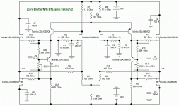
Re: jcarr - EmitterNFB BTL-amp - version 2
Okay, just want to know:
... if any new variants of this amp ??
from Jonathan Carr ??

jcarr said:The core idea is to use the gates/bases of JFET/BJTs for the signal inputs (per normal practice), but route the NFB loops through the sources/emitters of the same devices. If nothing else, this should allow one to utilize various inverting feedback configurations without having to rely on high-impedance series-input resistors for fear of loading down the source component excessively.
----------------- ----------
regards, jonathan carr
Nelson Pass said:I see that Fred has anticipated some of my thoughts and has addressed them.
This newer version will have a couple of things we want to pay attention to:
- It will want a balanced source for sure, and it will need a regulated supply,
as our PSRR has declined with the replacement of the negative side current source with a resistor.
- It might be reasonable to reinstate the current source in this spot.
- Also, I would be inclined to put back some Emitter resistance on the PNP transistors.
Okay, just want to know:
... if any new variants of this amp ??
from Jonathan Carr ??
jcarr said:Fred Dieckmann notified me that some of the component values in my original schematic were just too far out to be usable - like putting a decimal point on the wrong location. :-(
Here is a slightly cleaned-up schematic with what I hope are more appropriate component values. In the interest of staying with easily found parts, I replaced the current sources with resistors. But if you have access to a variety of constant-current devices, or are willing to roll your own CC circuit, the current sink under the input differential should be 6.4mA, while the current source feeding the second-stage should total 32.7mA.
BTW, my interest in the current thread lies in the use of global NFB through the emitters of the input devices. More specifically, being able to set one path for the input signal and a separate path for the feedback, without adding to the total device count. At this stage, I mainly want to understand fully how this method works. How the idea is applied, for example, non-inverting operation, inverting, feedback to the same side, feedback to the opposite side etc. is a topic of interest to be sure, but one for another day. Apologies if my initial comment about inverting-mode circuits was misleading to anyone.
regards, jonathan carr
Hello.
Anybody did build this amplifier from Mister Jonathan Carr ?
Like from image this one: http://www.diyaudio.com/forums/attachment.php?s=&postid=131751&stamp=1045710350
I can find Toshiba 2SK389, 2SK1529 and 2SJ200. No problem
But my question is if can I replace 2SA1360 transistors with other good transistors? What recommend you?
I will build myself MOSFET amplifier some model. But do not know best one.
Thanks for anybody your help
jac
The idea of returning the feedback to the emitter/Source in a solid state piece is quite old hat to anyone who is at all familiar with tubes. Scads of ancient tube designs do exactly that (to the cathode, obviously). Some even use feedback to both the grid (think base/Gate) and the cathode at the same time, using nested feedback from different points in the circuit.
Grey
Grey
electrofan said:hi again
what would happen if use two 2sk170 for input pair in the place of 2sk389
can i do this you think?
( I put as attached jcarr amplifier circuit )
Think you will get almost the same perfromance.
2SK170 is on level with 2SK389 in relevant parameters.
- Status
- This old topic is closed. If you want to reopen this topic, contact a moderator using the "Report Post" button.
- Home
- Amplifiers
- Solid State
- Source/emitter global NFB amp
