I just got this little guy in. The owner said it works -ok- but supposedly the switches on the bottom have some bad connections. Needless to say I'll probably try my best to restore this little guy!
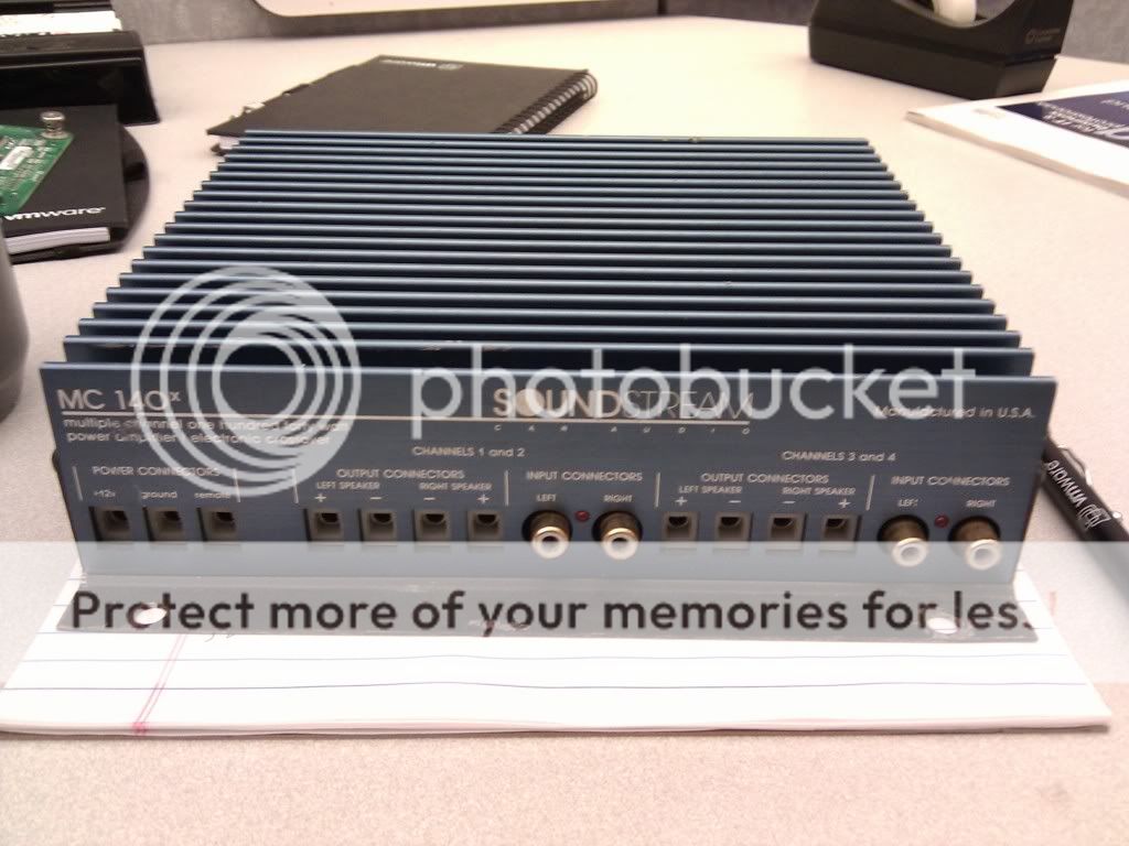
Soundstream MC 140x
Made in the USA
Supposedly 35w Rms, its a 4 channel amp
Looks like this little guy may have independant power for each side. 4 x 3A fuse holders. The amp currently has 5A fuses in it.
Was this a good little find?
Soundstream MC 140x
Made in the USA
Supposedly 35w Rms, its a 4 channel amp
Looks like this little guy may have independant power for each side. 4 x 3A fuse holders. The amp currently has 5A fuses in it.
Was this a good little find?
I like this little amp. Its very clean and clear. It has cleaner lines on the scope than my PPI PC275. I cleaned up all the switches so they dont make much noise. All the way through I couldnt find much of a problem with this amp on the bench so I decided to give it a whirl on my car for my door speakers. I set this amp to run it's four channels bridged down to two and wired it up to my door speakers.
With car off the sound was pretty crisp and clean, more than I would have expected. Problems only started when I turned the key one past ignition - then I started to hear my car's fuel pump whine through the speakers. I put my song on mute and sure enough it was apparent. I didnt get as far as to starting the engine; but I did notice that in bridged mode the gain controll for channel 3 wasnt working. The other 3 were. Then just 30 seconds later the soundstream popped channel 4's 5A fuse - I thought she was a goner but it's working again on the bench.
Does this amp maybe have a ground problem?
I also notice someone maybe even at the factory scraped through the trace under the PCB between channel's 1 and 2 RCA shields.
Well now this amp is playing some tricks on me. It sisnt make the noise in the car with test speakers, nor did it make the noise when I switched back to the door speakers. Yet another 5A fuse blew on me from channel 4 after I increased the volume to 2/3 maximum listening level (about 50% up on the HU).
After the fuse pops I smell burnt silicon. I'm having troble finding where its coming from but will keep looking.
After the fuse pops I smell burnt silicon. I'm having troble finding where its coming from but will keep looking.
Theres a ghost in this little amp. now, channel 3 doesnt have any audio on it. I think also channel 4's output transistors have seen better days. They smell like old-burnt silicon but they still play. I tried tracing a sin wave signal with my scope on Channel 3 and theres something just not quite right with how far the signal is going.
Perry,
Do you know what the 6 pin IC is on the non-solder side of the PCB? They look like little opamps or something, and are about 1/4 inch x 1/8 inch with 6 little spider legs coming off. Each channel has one of them. Can I test these with a dvm? They seem to measure the same between them, but for some reason I dont think my source signal is being passthrough right on Channel 3 through this little piece.
I'm also thinking of just buying all new output transistors for this amp, since Channel 4's smell funky. They are original, and I think they are TIP101/102 and TIP106/107 but will have to confirm after removing them.
Last edited:
Move the switches back and forth to see if channel 3 returns.
The 6-legged transistor may be a 2SC3067:
http://datasheet.octopart.com/2SC3067-Sanyo-datasheet-102206.pdf
You can check it with a meter but it's unlikely to be defective with the symptoms you described. Do you have audio on this transistor? If so, you may have a blown fuse or a problem with a relay.
Can you post a photo of the inside of the amp? I've never had to repair one of these so I don't know exactly what you have.


I've removed Channel's 3 and 4 output transistors. Not only because i thought they were bad, but because I also dont want to damage them if they are NOT bad.
I checked for audio on all pins of both channels 3 and 4 of the 3067. Something is definately up one if not both of these transistors.
On Channel 4 (Bottom of picture) I get audio signals only on the cornor pins on all but the bottom right pin (3?).
On channel 3 (Top of picture) I get audio only on the top right pin (4?).

[edit] ... Compared to channels 1 and 2 - 1 & 2 have audio on all 4 corners of the 3067. If the 3067's are malfunctioning I dont know where to get replacements.
The 6-legged transistor may be a 2SC3067:
http://datasheet.octopart.com/2SC306...eet-102206.pdf
You can check it with a meter but it's unlikely to be defective with the symptoms you described. Do you have audio on this transistor? If so, you may have a blown fuse or a problem with a relay.
I checked for audio on all pins of both channels 3 and 4 of the 3067. Something is definately up one if not both of these transistors.
On Channel 4 (Bottom of picture) I get audio signals only on the cornor pins on all but the bottom right pin (3?).
On channel 3 (Top of picture) I get audio only on the top right pin (4?).
[edit] ... Compared to channels 1 and 2 - 1 & 2 have audio on all 4 corners of the 3067. If the 3067's are malfunctioning I dont know where to get replacements.
Last edited:
AmpLabs? i dont think I need 20 of them though...
2SC3067 120V Matched Pair Transistors - Buy Online @ AmpsLab
Here is not too bad, but its eBay...
http://cgi.ebay.com/2SC3067-SANYO-N...528?pt=LH_DefaultDomain_0&hash=item255eb50100
2SC3067 120V Matched Pair Transistors - Buy Online @ AmpsLab
Here is not too bad, but its eBay...
http://cgi.ebay.com/2SC3067-SANYO-N...528?pt=LH_DefaultDomain_0&hash=item255eb50100
Last edited:

Does the amp have a bridging switch? If so, change it's position. Does that effect the signal on the transistor where you have signal on 2 legs?
These are inside the feedback loop. With the outputs out of the circuit, the readings on the 3067s (with the scope) are generally irrelevant.
The 3067s rarely fail catastrophically. They sometimes become mismatched and cause more than ideal DC offset.
These are inside the feedback loop. With the outputs out of the circuit, the readings on the 3067s (with the scope) are generally irrelevant.
The 3067s rarely fail catastrophically. They sometimes become mismatched and cause more than ideal DC offset.
Does the amp have a bridging switch? If so, change it's position. Does that effect the signal on the transistor where you have signal on 2 legs?
Before running this test I verified continuity of the stero/mono switch with my DVM. Confirmed switch works with continuity on desired pins at .5 ohms.
In stereo mode;
Channel 3's 3067 only has signal on pin 4. All pins except pins 1 and 6 have 0v DC, 4.7v AC. Pins 1 and 6 have 3.7v AC.
Channel 4's 3067 has signal on 3 corners, excluding pin 3 which has no signal. All pins have 0v DC, 4.7v AC.
For reference in stereo;
Channel 1 and 2's 3067 has signal on all 4 corners. All pins have 0v and 4.6-4.7v AC.
In Mono/Bridged mode;
Channel 3's 3067 shows no signal on any pins. All pins except pins 1 and 6 have 0v DC, 4.7v AC. Pins 1 and 6 have 3.7v AC.
Channel 4's 3067 has signal on 3 corners, excluding pin 3 which has no signal. All pins have 0v DC, 4.7v AC.
For reference in bridged;
Channel 1's 3067 gets no signal, but has 4.7v AC
Channel 2's 3067 has signal on all 4 corners, and has 4.7v AC.
How can a point have no signal AND have AC voltage?
In bridged mode, it's likely normal to have no visible signal on the differential (the 3067 contains the transistors for the differential amp) for the inverted channel.
You can't compare the channels with and without outputs.
In bridged mode, it's likely normal to have no visible signal on the differential (the 3067 contains the transistors for the differential amp) for the inverted channel.
You can't compare the channels with and without outputs.
How can a point have no signal AND have AC voltage?
I'm really not sure. I use the scope to show the signal/sin wave, and a DVM to measure the voltage. Both referencing common ground of the amp. I'll have to play with this a little more and get back to you with why it came out like this.
I'm also thinking of maybe using the shotgun approach with this amp. If I replace all 4 channel's transistors (P102,P107,MPSA42,3067) it will only cost me about $15. I've still got to source the switches. Of course I would like to be more patient and solve the real problem before doing this but its an option. I only bought this amp for $10.
I think it would be better to reinstall the outputs and then look for signal on various points to determine why one channel is not producing output.
Replacing a lot of parts is sometimes faster and more profitable (when doing work for others) but you won't learn much doing it that way. If the problem was intermittent and it happened to work after replacing all of those parts, you may think it's been repaired only to have the channel go out again.
Some amplifiers have secondaries that are 100% isolated from the amp ground (this amp may have 100% isolation). When measuring voltage on the secondary side of the power supply, you should use the non-bridging speaker terminals, the secondary center tap or the RCA shield as the reference. Connecting the signal source ground to the power supply ground and having the signal source plugged into the RCAs on the amp can prevent errors and confusion on amps with secondaries that are 100% isolated from the amp ground.
I put the transistors back in. I think I may have found something a little strange. In the top-view picture above of Channel 3, I think I found the two glass diodes just to the left of center to be shorted. Diode check fails on both of them. Its either the diodes or the MPSA42 just to the right of the diodes. The resistor in the middle is still good. Comparing these diodes to the other 3 channels identifies this area to be faulty on channel 3. I'm gonna pull one of them and find out for certain.
What kind of diodes are these? Can I substitue or should I run over to RS?
I think I still need new output transistors. Channel 4 likes to run them hot, especially when I start testing signals out with a scope. They are stil good, but they keep poping fuses. I suspect its because of channel 3?
What kind of diodes are these? Can I substitue or should I run over to RS?
I think I still need new output transistors. Channel 4 likes to run them hot, especially when I start testing signals out with a scope. They are stil good, but they keep poping fuses. I suspect its because of channel 3?
Just as I suspected! Both diodes are shorted. They measure 0 ohms in both directions with the DVM and they fail Diode check with my Fluke 10. Number is 1N4148 on both. I pulled them both off the board and now I can probably check for other faults on other components.
Last edited:
- Status
- This old topic is closed. If you want to reopen this topic, contact a moderator using the "Report Post" button.
- Home
- General Interest
- Car Audio
- Soundstream MC 140x any good?