Some car audio speaker retailers refer to a Whizzer attached driver as a 2way speaker !
Auri sacra fames, as the old Romans put it so well ("Damned Lust for Gold" for the non-classic scholars).
Nige, come on now, a report on the meeting you went to, please.
That hi fi show . I put in motion something which I doubt will get anywhere . I was talking to my newspaper friend Paul Stewart ( ex JVC , Mobile Fidelity ) . We agreed vinyl is what kids might be interested by . We must bring new blood into our industry . One lad who works in the company said it is all too expensive .
The show was the most me too thing I have ever seen ( me too was the drugs industry who must copy withing the rules) . The nearest I got to excited by was not thinking a 300 B was waste of money when driving a 805 . Suddenly the bass end was OK .
I was asked to checkout a PS Audio P10 power plant . I very much approve as a piece of engineering . As far as I can tell it slices the top off of the mains waveform and inserts a low distortion top wave . This saves much heat in doing full regeneration . The interesting thing is they offer a choice of output voltage ( ie 240 not 230 ) . That might suit a very small number of tube amps ( goodness help the sales office trying to say what is best ) . The contentious one is a waveform that the P10 offers to demagnetize the transformer ahead of the P10 . Easy to do . I doubt soft iron does magnetize . It must a little I guess ? Andrew you must know this ?
Last edited:
Chaps , I should keep quiet about this . My hairdresser brought her El-cheapo " hi fi " to fix . Initially it had no output yet was not broken ( sounded like 0.1 watts ) . I had some high grade speaker foam ( Thomas Fast's damping foam for room treatment ) . It was too small to be useful and too nice to throw away , the exact size required . In it goes into the speakers . Vastly more output !!!!!!! Painted the cones with PVA avoiding the surround . What do you know , It starts to sound OK . I am listening to a string quartet without hating it . I had to do the silvered dome because I over shot ( 10 % water ) . Reckon that helps . I doubt it took me 20 minutes .
I won't do the posh whizzers of mine as that's too risky and HF . Tempting . Discovered this when repairing valve radios with ripped cones ( Rizla paper to the cone back to retain the 1940's look ) . They always sounded better with tons more bass . It retains the good qualities of paper . The water is to ensure it goes on thin and penetrates . PVA is wood glue . I seem to remember polypropylene when Spendor had PVA in addition . When my houses needed re-plastering PVA was what made old stick to new . If not everything would have been taken back to bare brick . Chicken wire to join the cracks caused by an ill fitting door .
I won't do the posh whizzers of mine as that's too risky and HF . Tempting . Discovered this when repairing valve radios with ripped cones ( Rizla paper to the cone back to retain the 1940's look ) . They always sounded better with tons more bass . It retains the good qualities of paper . The water is to ensure it goes on thin and penetrates . PVA is wood glue . I seem to remember polypropylene when Spendor had PVA in addition . When my houses needed re-plastering PVA was what made old stick to new . If not everything would have been taken back to bare brick . Chicken wire to join the cracks caused by an ill fitting door .
Over in the full range ( miss-named, should be "limited range") forum, doping cones is a frequent topic. I am sure many of us have use PVA or RTV at some time in the past to make a 49 cent driver work like a 79 cent driver. Yes, it can be quite an improvement. Or it can be quite a disaster. You don't know unless you try. Just don;t do this to a good ScanSpeak.
New arrivals!
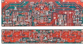
Finally, my power amp project is ready to take off. I just received the printed ciruit boards, two per side.
In the end, it turned out that it had to soplit into two piggyback boards if everything I wanted was to happen. And I was not shy with my desires.
Have you noticed that just about every, i.e. 99.999% of all projects shown on Internet are in fact defficient with what I consider to be some essentials? For example, how many offer even basic overheat or excess DC protection? It seems taken for granted that the DIYer is really a dummy and isn0t worth the time and trouble. So many DIYers run the risk of using not very safe devices for many reasons, starting with designer negligence.
Well, I went the other way. My idea was not only to go for some serious sound, but to make the package complete all around. Then I realized that making a number of small boards WILL be a problem for many, which meant that it had to be all packaged into as simple a package as possible. Actually, it COULD have all been packed on one board if the board were somewhat bigger, but that would have meant forcing the board-heatink height to around 6 inches (15 cm), which means that the case would have to be say 8 inches (18 cm) high, and by audio standards, that's fairly high and consequently more expensive.
Also, by piggybacking the boards along the heatsink, one eventually ends up with a completely self-sufficient power module, its only external part being the current amp power supply (rectifiers and caps). I could habe bolted that on too, but I felt some might find that a bit too constricting in their choice of the type and number of filter caps. A board has been designed and will be made a part of the project.
The bottom (small) board will accept three pairs of Toshiba/Motorola devices, such as 2SC5200/2SA1943, or in my case, Motorola MJL 3281/1302, which I swear by. That's fairly generous for a nominally 100 W/8 Ohms amp, which should deliver 190 W into 4 Ohms and around 270 W into 3 Ohms, where its continuous full power delivery ends with the heta sinks I plan to use. But it should also be capable of delivering impulse power peaks (app. 40 mS) into 2 Ohms of around 540 Watts, using the Motorola debices, specified at 200W each, as opposed to Toshiba's devices, which are specified at 150W each.
I have tried VERY hard to use easily obtainable off the shelf devices, with what I'd call normal prices. I hate projects which use damn hard to obtain parts, which in bthe end always cost an arm and a leg.
Other than that, the only unusual aspect is that each output device has a 2.200 uF/63V cap stuck no more than 3 mm (0.11 inches) from it; of course, this is in addition to 4 x 10,000 uF as the usual power bank. The point is, easch transistor can draw ober 2 Amps of current practically next to it, meaning in almost zero time and under almost ideal conditions.
The bigger "upper" board comtains the rest, this being the input stage, a current mirror and the complementary VAS. This is fed by a locally regulated symmetrical power based on the "virtual battery" idea, promoted by some Japanese manufacturers (e.g. Technics/Matsushita) not too long ago. I tried it and, believe it or not, found to to be better than just about any other electronically regulated power supply I had ever tried. Simple is often the best. Obviously, the IPS/VAS PSU lines are higher that the current PSU lines, thus nulling and interference from the current stages. BTW, the predrivers are also fed from this stabilized stage, providing for a very stable drive point.
You might notice some unusual blocks on the big board. "Protection area" contains circuits protecting from overheating and excessive DC, and they do so by opening the output relay. The overvoltage and overcurrent circuits are integrated into the whole to the right and center. Then comes the "Level Meter Area", which uses an LM 339 quad comparator and has outputs for 4 LEDs - for "Power On", for "Signal Present", for "0 dB VU" (full nominal power) and "Clip", meaning back off hombre, you're frying the amp.
Lastly, to the extreme left and right sides you see the said power regulator, and above them are spaces for 3+3 filter caps, with space for up to 6,800 uF caps, depending on the voltages you plan to use.
Electronically, it's a fair do, nothing particularly wild about it, except perhaps the open loop full power bandwidth, which extends to around 70 kHz into 4 Ohms. I cannot be definite about it yet, simulations are nice, but to say anything I have to play around with a real world model for a while.
Initially, i ws going to go for a DC Servo as well, but eventually decided to go for an AC coupled model. This was because by talking to people, I realized there was much misunderstanding of AC and DC coupling among the DIY ceowd, and that they somehow mistrusted servos. I don't see why, but this time, I bow to the view of the majority, as this is not all for myself, rather it's mostly for others.
Once I have tested it to my satisfaction and made a selection of parts I can recommend, I will put the entire project in public domain, obviously including the gerber files, everybody has to be able to make completely without me.
Attachments
My thoughts exactly . For the old radio it is the only answer . Somehow better than plastic cones regardless. I notice most paper cones have similar from new these days .
I hope my hairdresser likes it ( she will ) . As she says it gives her some music . Looks cool as you say .
An Altec unit wouldn't get this treatment , tweeter especailly . They are just perfect anyway ( you know what I mean , perfect of type ) . They look cheap and sound expensive .
I hope my hairdresser likes it ( she will ) . As she says it gives her some music . Looks cool as you say .
An Altec unit wouldn't get this treatment , tweeter especailly . They are just perfect anyway ( you know what I mean , perfect of type ) . They look cheap and sound expensive .
Oh yeah, given its nominal power of 100W/8 Ohms, I named it "The Centurion".
The artwork was done by a friend from Romania, Alex. I feel his work explains why it's called ARTwork. He's phenomenal. God bless the Internet!
Well done .
I will when time permits do my Land-rover amp design . Nothing more than a Quad 303 with ability to drive 1 R . I will do a little bit of extra design to make it easier to set up . Unlike Linn and Thorens ( is AR ) I will be honest enough to say 303 inspired . I think I will go for all NPN TO3 with capacitor coupling . I am convinced it has more good than bad in it . I am also convinced it need not have any sonic imperfection that any real human can hear . It must drive fairground speakers as a Carlsbro would ( a specialist make ) . My baffle speakers must have that sound if pushed . I have the Maggies when required to judge accuracy .
DVV,
Why the same size caps at the outputs , as the mains and whats with all the dynamic killing speaker protection duh ..!!!
Beacuse they can be nicely joined, using the same screws for both - don't worry, Wayne, I did think this one out, by the age of 60, I have learnt to control my impulses to just make and then go through 2, 3 or 4 variants before I get to where I should have been initially.
The protection circuitry is not "dynamic killing" at all, brother Wayne. If you ever did manufacturing, you would know that when designing anything, you have to think about the lowest common denominators, meaning the worst case dummy you can imagine. That's one thing.
The second is a question - how many people do you know who sit in their rooms, listening to their evil load speakers reproducing steady state sine waves? I've met many people, but never one like that. Ultimately, you have to leave some headroom for the transients, and if listening to full power steady state, you have zero headroom, so the first transient at best blows the fuse, at worst it blows the speaker. Right or wrong?
And lastly, I have made sure that if you were to completely leave out the overvoltage/overcurrent circuitry, NOTHING would happen, the amp will go on working as before. Therefore, if you for example insist on taking a chance, you just leave it out. For that matter, leave everything but the amp circuitry out, you do not operationally need it, it's there only to make you safer and to safeguard both the amp and the speakers.
And there will be variants. I simulated the same circuit (with changed values, of course) from +/- 51V to +/- 58V for the current stage and correspondingly higher VAS stage. At the maximum, which is the maximum ONLY because I wanted to keep it within the reach of the 63V cap class, as in Europe, higher starts to become painfully expensive. Works like a charm.
With +/-63V for the VAS and +/-58V for the current stages, it will deliver peaks of 170W into 8 Ohms, which is roughly +22 dBW overall, which would in theory allow my own speakers +22 dB above their nominal 92 dB, or 114 dB. In theory, in real life that's probably more like 111 dB or so. Dynamic room enough with the protection circuitry in and on.
As I see it Wayne, my job is to allow for the possibilities, and it's up to the user to choose those he wants and those he doesn't want. So, for known higher speaker impedances, he can use higher voltage version, and in your case, the lower voltage version would be better served, as it would allow more current capability.
As for the caps, the ones you see there are only LOCAL caps. Preceeding them is a series of lower values (also on board), including one RC filter, and at the rectifier, there are two 10,000 uF/63V caps per each supply line, or, in a stereo amp, a total of 80,000 uF.
If you were to add up the main and local caps, each current supply line is filtered by (2x10,000)+(3x2,200) 16,600 uF, or a total of 106,400 uF for a stereo amp.
The entire idea of having local caps by the output devices is aimed at improving the amp's dynamics. Both by being next to the user (power trannies) and by the fact that if looked at the entire series from the rectifier to the first next power transistor, you have the following row:
10,000 uF - 10,000 uF - 100 uF - 3.3 uF - 220 nF - 1R in series with 470 nF - local 2,200 uF.
If that doesn't work, I honestly don't know what will. The only "sliding" value here is the series 1 Ohm + 470 nF. That's supposed to get rid of residual large capacitor inductance, but the actual value of the cap will be determined by the size, type and quality of the large caps used. 470 nF is a tentative value only.
I have given the Land-rover ( Hummer ) amp some thought . +/- PSU . It realistically needs 50 x 220 uF 35 V non polar to work this way ( 100 total ) . They are cheap enough so no problem . Will look great with the lid off . There can be a direct terminal for domestic use . The 35 V rating limits me to 100 watts 8 R . If anyone knows of big non polar > 35 V that would be good . I guess capacitor coupling is too easy ? None the less that suits me .
Like a Land-rover it will be so boring , it will be unworthy of much discussion . However when the going gets rough it should smile . The Land-rover is mostly a 1947 design . What it does well seems not to be understood by imitators .
DVV you are 100 miles up the road on this . Yes I will take out every part I can . I have a design spec in mind so no part removed it needs .
The PSU will be 2 x 47 000 uF 63 V as I have some ( BBH ) . The outputs for now 2N3055 E ( not H , some prefer E ) as I have 20 . I have a massive pre drilled heat sink of 0.25 degree per watt ( guess , was for 1000 watt PA amp ) . Spec should be 1 Hz to 100 kHz - 2 dB . - 80 dB distortion from 1 mW to 80 W rms 8 R . Hum - 85 dB reference 1 watt . Hiss - 100 dB reference 1 watt ( Quad was - 112 db when measured late in it's life reference 45 watts ) . 1 R ability . The only mod over Quad is to run the VAS hotter to drive extra outputs . Run drivers hotter also . Bias cool as the Quad . LTP input . It will have the same primitive current limiting as I find it works .
Last edited:
BTW . This is nothing to do with cars really . However lets take three I love . Ferrari , Land-rover , VW Passat estate TDi . The VW is probably the best car in the world . The reason is it gets you there safely at extremely high speed whilst sipping the fuel . It will even go shopping for men's stuff from the builders merchant . It is enough like it's stablemates right up to Lamborghini to have finesse .
All of this is irrelevant . Thus it is a shoot out between the other two . Real life has rebelled and the Ferrari is seen as an odd toy . We in hi fi seem not yet to have understood this . The customer talks Ferrari yet wants a Land- rover in their dreams . Having listened to a big Pioneer it is the Passat .
DVV . With no insult you make Land-rovers and you should be very happy .
My hairdressers Boom box in boxes is sounding rather good . Who would dare hope for that ! Thank you Thomas Fast for the foam .
Nige, there's nothing insulting - in fact, quite the opposite! - by comparing one with the Land Rover. An iconic name and company, the first aluminium vehicle which could not rust (well, mostly) and could get you almost anywhere, but always further than others. You are too kind, Nige, I know I am not nearly that class, I think only JC is, after all these years, he doesn't need to prove anything, his works speak well enough of him.
And, at least the two us know the truth - you make it and then pluck out everything you can until it stops workig, then you return the last part. I make it, and then start adding bells and whistles for this or that.
No-one is right or wrong here, we simply have different approaches, and only the final products can testify honorably who did it better this time. I've never thought of anyone with a different approach to audio as mad, nutty, crazy or even wrong - I respect a man who has his own standpoint no matter what I or anyone else think of it, so long as he can show creditable results for it.
As for being happy, it's too early to tell. Technologically, I am happy, but the point is not the technology, which is only the means to an end, but how the end product sounds. If I find it worth the time and trouble, then I will be happy indeed.
And I would like to thank just about everybody here for their comments and discussions on audio electronics, I have tried to incorporate several comments read here I though were desirable modifications to my own views.
As ever, Thorsten's comments and on occasion bullying helped a lot. I don't mind the bullying, for 11 years I have known he means well, all I can do is thank him for his time, trouble and persistence in explaining why he thinks as he does. I wish I had met him 20 years earlier.
And some of Nige is built in too. His loose thinking has led him to ask a few questions I had to sweat to answer, but they also made me think and sometimes rethink a few things. Like warning me to investigate especially well how the 20 dB of global NFB tracks as very high requencies, that sort of thing.
As for the caps, the ones you see there are only LOCAL caps. Preceeding them is a series of lower values (also on board), including one RC filter, and at the rectifier, there are two 10,000 uF/63V caps per each supply line, or, in a stereo amp, a total of 80,000 uF.
If you were to add up the main and local caps, each current supply line is filtered by (2x10,000)+(3x2,200) 16,600 uF, or a total of 106,400 uF for a stereo amp.
The entire idea of having local caps by the output devices is aimed at improving the amp's dynamics. Both by being next to the user (power trannies) and by the fact that if looked at the entire series from the rectifier to the first next power transistor, you have the following row:
10,000 uF - 10,000 uF - 100 uF - 3.3 uF - 220 nF - 1R in series with 470 nF - local 2,200 uF.
If that doesn't work, I honestly don't know what will. The only "sliding" value here is the series 1 Ohm + 470 nF. That's supposed to get rid of residual large capacitor inductance, but the actual value of the cap will be determined by the size, type and quality of the large caps used. 470 nF is a tentative value only.
My issues is not the values used at the outputs , why not smaller value at outputs say 4,000 uf and larger values at main supply.
Also regardless of how you design the circuit my experience has been they kill dynamics , i have seen this with the newer Krell and Halo amplfiers, the Older amplfiers with no such device dont have such issues so yes i would like it out ...
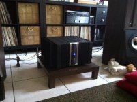
If not i would have to kotch the relay , like with this one ...
")
Edit: Ok i read thru ur explanation again and see where you are going with the caps , at your operating voltage i would like a bit more in the main supply....
Attachments
Last edited:
D,
How long before you have this thing going or is Nige Sethwright the Guinea pig...
No way to tell, Wayne. If I hit the jackpot, a week or two, normally about two months, if with bad luck say 3 months. The hardest, but also the nicest part of a project is the development, after you have established that the whole is electrically fine. Development is really tuning it for the sound you want.
Re: protection circuits. I beg to disagree. While protection circuits can be a problem, and are in cheap commercial units where lower power and hence cheaper output transistors are used stretched almost to their limits even under normal conditions, such ciruits will be a problem simply because they have to kick in too early or the output stage is toast. Just doing their job, the fault is the basic design which does not do justice to complex loads by design.
The one I used in the Centurion will let the amp deliver its full rated power steady state down to 3 Ohms - that's how much leeway I have with three pairs. However, in short term peaks, it will do 2 Ohms easily at TWICE the time limit set by the IEC standards. Assuming you have left 6 dB of headroom for transients, you should never ever have the protection circuits turn on.
As for the size of the caps, aren't you running wild there a bit? 2,200 uF is good for about 2.5 Amps if the caps are relatively good quality. Trust me on this, that's MORE than sufficient, you have a total of 26,600 uF per supply line or 53,200 uF per channel in a dual mono configuration. Possibly more if you gor for say 12,000 or 15,000 uF main caps. So, knock yourself out, but I want to go on record as saying this - with what I initially intended, you have little to gain by adding more, but you do need a hefty power transformer. Minimum 400 VA per side, 500 VA preferred and recommended.
Lots of caps won't do diddly unless their voltage/current source is both big and good enough.
Massive cap banks are often a cover-up for modest transformers. They help ride out the peaks, but it's still a cover-up.
D,
How long before you have this thing going or is Nige Sethwright the Guinea pig...
If I was LJK Setright I would be proud . What a name .
" It also borrows a quote from legendary British automotive journalist L.J.K. Setright, one we're going to borrow as well. Writing in 1979, Setright was eulogizing the Series Land Rovers, but his words are timeless and could be just as well applied to the Defender "
Spen King used to phone me about the Garrard 401's . He would never give his name but talk all day about Land Rovers and said he had Jet One at home when young . He let slip one day he designed the Range Rover .
http://www.google.co.uk/imgres?imgu...a=X&ei=9QpDUu_rHYLMhAey2YGABg&ved=0CDkQ9QEwAg
Last edited:
- Status
- Not open for further replies.
- Home
- Member Areas
- The Lounge
- Sound Quality Vs. Measurements