Well that's just one way to constrain Z and ESR, and C. But maybe sometimes another type of constraint might be dominant so you have to check to see. What about PSRR for example?
And although i used DC at the peak level as the worst case, which means it covers even the lowest bass frequencies, the resulting C value is guaranteed to be overkill, to some degree, so, for a given "lowest frequency" requirement greater than zero, the C could be reduced, which would probably be necessary for any commercial design.
And of course I also didn't touch on the high-frequency constraints, which provide the plot of the maximum acceptable impedance versus frequency that the output device must see, to be able to slew at the device's capability, and accurately reproduce transients, and run the feedback mechanism fast enough. The results of that analysis boil down to combinations of decoupling capacitances and their maximum acceptable inductances and ESRs, which boil down to how far from the point of load they can be, and how many in parallel need to be used.
Last edited:
And, the short answer is: below 10 milliohms is what I aim at, which can be achieved by paralleling enough caps, with leads no longer than necessary. Don't like screw terminals or axials, I always use radials.
Sorry, Tom ...
No baby caps here all big bwoy screw type ....
@Tom,
Thanks for the education Tom, did anyone take a look at the link i posted , easy technique when wanting to measuring ESR ...
Thanks Tom for the worksheet.
It gives some pretty high values for the caps, so I have some questions:
It gives some pretty high values for the caps, so I have some questions:
- Should rail voltage be the voltage across both rails, e.g. +/- 24V = 48V rail?
- Is the capacitance total, or per rail?
- If per rail, then should only that rail voltage be entered and the cap value used on each rail?
Hi Pano. I'm sorry that the instructions were not more explicit. Yeah, it's all per rail. So you just enter one rail voltage and the capacitances are then per rail.
The cap values don't change unless you change the ratio of rated max power / theoretical (i.e. zero ripple) max power. Those are in the blue row, row 10. You are allowed to change anything that's blue.
That was one of the "Aha!" things I found and is one of the reasons I decided to put together that spreadsheet. The ratio of Max p-p Ripple / Max Output Peak Voltage is another one that doesn't change when supply voltage or load impedance is changed.
If you want particular capacitance values in row 21 (green), you can use Excel's "What if" feature, and tell it to change row 10 to make row 21 whatever you want, in the particular column you're in. Or, of course, you can also just change row 10 manually.
Using the "What if" feature of Excel is nice, there, if, for example, you want to see the effect on max rated power for different numbers of the same value cap in parallel, such as, say, one to fourteen 4700 uF caps, or whatever value you want. (But it doesn't divide the ESR or inductance by the number of caps, or anything like that.)
Last edited:
Hi SY,
I can see how the trace or lead resistance could be as significant as ESR, and maybe greater than the ESR. But "swamped by" might be a bit of a stretch. I always considered "swamped by" to mean that the other thing was at least ten times the original thing. I guess if we paralleled a lot of low-ESR caps, the trace or lead resistance could swamp the resulting lower aggregate ESR.
Lower ESR is not always better. One situation where that could be true might be when there's a possibility of an LC resonance and more ESR could help to damp it. (Frank hates that example.) But for PSU reservoir caps, it's difficult for me to imagine a case where lower ESR would be worse.
And since there is additional resistance, in the traces or leads, that would make it that much more difficult to meet a target impedance requirement, which might mean that we would need to use caps with lower ESRs than we thought, before we considered the parasitic resistance of the traces or leads.
Maybe I should add a parameter for the resistance of the connection to the point of load, to the equations I posted, summing the connection resistance with the ESR. That might at least make it more obvious that there might be some cost associated with putting the PSU too far away from the output devices. I guess I should also add the connections' inductance effects, since they can cause significant ripple for fast-changing currents. Maybe then people would realize why they should use sufficient decoupling caps, close-enough to the point of load.
I did actually write the differential equations for a transformer (with winding resistances and inductances), rectifier, capacitor, and amplifier with resistive load with constant current. They can't be solved in closed form with approximating, so I created a numerical solution that runs in Excel. It was my first VBA programming. It also includes a scalable transformer model, which is pretty neat. And I borrowed some code to make the plot zoom-able by mouse-dragging a rectangle on it, and then added the ability to measure the plot, similarly, like you can in LT-Spice.
It's useful for looking at startup behavior, and also calculated things like the worst-case ripple amplitude, peak output, and the peak currents in the caps and diodes. It can be downloaded from:
http://www.diyaudio.com/forums/power-supplies/216409-power-supply-resevoir-size-167.html#post3287619
Cheers,
Tom
Last edited:
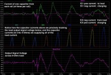
Well "ripple current" is what we want, anyway. It's just the current that becomes the music, since the music signal IS the current that flows from the reservoir (and decoupling) caps. So any "ripple current" will have been commanded by us, and will be in quantities that we desire.
And with lower ESR, the music current that the caps supply will cause lower ripple voltages. And we primarily want agile and robust current-supply capability, with a secondary goal being to disturb the rail voltages as little as possible.
The attachment shows the capacitors supplying the current that becomes the music, directly. (I used a WAV file of the intro from "Highway to Hell" as an input, in LT-Spice.)
Attachments
Last edited:
<snipped>
They can't be solved in closed form with approximating, so I created a numerical solution that runs in Excel.
<snipped>
Tom
That should have been "without approximating".
The only way they CAN be solved is with the use of at least one approximation. The main difficulty is probably that it always comes down to trying to determine when the input sine intersects the decaying exponential of the cap voltage. And that is a transcendental equation with no closed-form solution. I could have approximated the sine with a parabola, using the first couple of terms of its Taylor Series expansion. But I figured that a spreadsheet would be more useful, anyway, and that it would be a good learning experience for me.
There's also an Excel 97-2003 version, at http://www.diyaudio.com/forums/power-supplies/216409-power-supply-resevoir-size-166.html#post3282260 . It has everything that the 2007 version has, except for the plot Measure capability, because I was too lazy to add it to that version.
There is a short write-up about it, with the derivation of the equations, at:
http://www.diyaudio.com/forums/power-supplies/216409-power-supply-resevoir-size-166.html#post3279883
The full VBA code is available in the spreadsheet itself.
Last edited:
My Perreaux 2150B was badly crippled because it relied on a couple of big mutha screw caps - in the end I gave trying to work around them, threw them in the spares bin, and put in lots of "baby caps" -- it then started to give me the dynamics I was looking for.No baby caps here all big bwoy screw type ....
ME amplifiers, Krell killers from Oz, relied on the multiple "babies" way ...
Gosh, Tom, don't need you giving me a hard time! ...Lower ESR is not always better. One situation where that could be true might be when there's a possibility of an LC resonance and more ESR could help to damp it. (Frank hates that example.) But for PSU reservoir caps, it's difficult for me to imagine a case where lower ESR would be worse.
,LC resonance can always be kept under control with, you know, proper design,
... . I fight for every last bit of lowered ESR, because simulations easily demonstrate the benefit of doing this in the power supply area.Ha! Moi??! Not giving you a hard time, Frank, UNLESS you're still not ready to admit the possibility that large electros and parallel film caps could form an LC resonance and are therefore usually not a good idea. That's the only "engineering fact" I can remember us disagreeing about, back in the "Power Supply Reservoir Size" thread. I'm guessing that you never found the energy to read through the tome that is also known as the thread called "Paralleling Electrolytic and Film Caps".
That's the only "engineering fact" I can remember us disagreeing about, back in the "Power Supply Reservoir Size" thread. I'm guessing that you never found the energy to read through the tome that is also known as the thread called "Paralleling Electrolytic and Film Caps".Remember, lower ESR can mean higher ripple current. 100 milliohms in not unheard of for track resistance.
100 milliOhms? Wow. I usually estimate about one mΩ per inch, for PCB traces and small-ish wires. In that case, we'd need 100 inches to get 100 mΩ! That's 2.54 meters!
R = ρ∙L/A,
where R is in Ohms, the conductivity of copper, ρ, is 1.68×10⁻⁸ Ohm-meters (where 1.68×10−8 = 0.0000000168), L is length in meters, and A is cross-sectional area in square meters.
From that, the Ohms per meter of a copper conductor would be
Ω/m = 0.0168 / (area in sq mm).
To get 0.1 Ohms from 12 inches of conductor, which is about 0.3048 meters, the Ohms per meter would be
0.1 / 0.3048 = 0.3281 Ohms per meter.
So
0.3281 = 0.0168 / sq mm
sq mm = 0.0168 / 0.3281 = 0.0512 sq mm
That would be a very small PCB trace.
If that was a circular wire, its radius would have to be
r = √(0.0512 / π)
r = 0.1277 mm
diameter = 0.255 mm, or about 0.010 inch.
AWG 33?
Actually, energy is one thing that I'm in genuinely short supply of these days - I stupidly overcooked my brain fighting those damn computers, and Microsoft,Ha! Moi??! Not giving you a hard time, Frank, UNLESS you're still not ready to admit the possibility that large electros and parallel film caps could form an LC resonance and are therefore usually not a good idea.
, and my mental stamina now is very poor, compared to what it was some years ago.Anyway, not roasted enough to not still be able to bite the bullet on LC resonance: electros have enough ESR in their own right, as a ratio to their capacitance value, to always damp any resonance - Ben Duncan described precisely the situation over 20 years ago, Spice makes it easy to model the behaviour - it's film caps electrically "near" to other films that can get you into trouble ...
Last edited:
ME amplifiers, Krell killers from Oz, relied on the multiple "babies" way ...
+1 for the 'legion of babies' approach. I liked Terry Given's 'capacitor carpet' a lot but I've been wondering for some time if there isn't a more efficient way to do it in 3D - like a buckyball of caps
I got me one of them! It was a hoot putting it together - tiny, low ESR Rubycons, a squash ball of caps!I liked Terry Given's 'capacitor carpet' a lot but I've been wondering for some time if there isn't a more efficient way to do it in 3D - like a buckyball of caps
Never actually used it, the reason for doing so went away - now a peculiar 'insect' in the leftovers bin ...
+1 for the 'legion of babies' approach. I liked Terry Given's 'capacitor carpet' a lot but I've been wondering for some time if there isn't a more efficient way to do it in 3D - like a buckyball of caps
I have been wondering about ways to connect multiple parallel caps, too. I did see a project of yours on another forum, with lots of different 3D cap arrangements. Impressive.
If you use n smaller caps in parallel, and could somehow keep their leads and connections from having mutual inductance, it turns out that they can be farther away than you might think and still provide an inductance and ESR advantage (like, even n caps at n times as far away as one cap is not a wash, if I recall correctly). But you can't prevent the mutual inductance, very easily, so you don't get the full reduction to 1/n inductance.
So maybe the best way is with a plane, like Terry did it. But I think it would be better if the load was at the center of a circular plane and the power feed was distributed evenly around the periphery, for even lower mutual inductance effects. Or part of a circle could be used.
So maybe some cone-shaped PCB full of caps, with the "pointy end" at the load, and the power feed distributed around the circle at the other end? And then use multiple cones to fill an approximate half sphere? Then put your amplifier board between two of those half spheres? Maybe the very thin flexible PCB material could be used. Mount the caps and then shape it into a cone, with something rigid (and maybe cone-shaped) to hold it in place.
Sounds crazy but who knows?
Or just make several boards like Terry made, for each rail. The trick would be connecting them with low inductance. If you made a cube of them, would a blank two-sided PCB connected all along one whole side of the cube be able to function as a low-inductance path (and another one on the other side to distribute the input from the rectifiers)? Would paralleling multiple boards, to make the cube, lower the inductance even more than a single larger board? I guess it would if the boards could be connected well-enough, e.g. with the solid planes mentioned, and if the mutual inductance wasn't a problem.
Or would the mutual inductance be minimized better if the boards were arranged radially, with only one edge approaching (parallel to) the other boards' edges, near the center? But then how could we make a low-inductance connection to the load? Where the edges almost meet would be nice but I can't immediately think of a good way to do it, there. Aha, maybe sit the whole radial assembly with all of the boards' bottom edges almost touching a blank two-sided PCB, and connect all of the ground sides to one side of the "base" pcb and all of the power sides to the other side of the base pcb. For the connections to the top of the base pcb, pieces of copper could be bent into long L-shaped pieces, as long as the boards, and soldered along their whole length. But to go through to the other side of the base pcb, maybe dense pin connectors, along the whole edge of each vertical radial pcb, would be enough to not raise the inductance too much? Maybe not. Or maybe wedge-shaped pcbs that could fit into the radial gaps would make it easier, since L-shaped copper pieces could then reach both sides of each board.
I guess the base couldn't be a full circle or else there wouldn't be any room for heatsinks on the amplifier. Maybe two half circles would work, one for each rail, stacked close together with their base pcbs parallel.
Or, maybe using no pcb would end up being more efficient, and easier. maybe there's some good way to connect some number of caps in parallel, and maybe then multiple sets of those could be connected, and then multiple sets of THOSE, and so on, to form some optimal tree-like hemispherical-sector-shaped structure with two leads at the base. I just don't know how the mutual inductance could be minimized enough. Could using multiple twisted pairs help?
If all of the leads ended up extremely short, maybe not much else would matter, for metal-sheathed caps like electrolytics. But that would necessarily be on a smaller scale. So maybe just making a hemispherical cluster of electros, just to take the place of a single one, would be worthwhile to try, too. It would probably have to be mounted from the bottom of an amplifier board but that's OK. Or mount one on EACH side.
Even just a circle of horizontal caps with leads meeting in the center would give really-short paths. Stacking multiple circles like that, to make a short cylinder, might make it better.
What if the power and ground both entered at the top of the cylinder stack and emerged at the bottom, at the load??
Maybe a strip of two-sided PCB could form the core of the cylinder.
Maybe circular pcb planes like Terry's could be stacked to form a cylinder.
Maybe a flexible two-sided PCB could somehow be wrapped around the outside of the cylinder, to form the rails. (Maybe for DIY it could be a little less perfect than that.)
If running the power and ground rails on separate PCBs wouldn't hurt (but it probably would), it would be much easier to construct something like that, using a square cylinder arrangement, since then solid planes to connect all of the inner planes would be much easier to connect, along two sides for the output and two sides for the input. Then you could balance it on one corner, at the load.
I have some way-better ideas that would be much easier to implement. But they involve things like shallow trays of liquid mercury with immersed board edges.
Last edited:
I suppose a "capacitor sandwich" is a bunch of axial caps stuck between two blank (full plane of copper) PCBs with holes for leads drilled in the appropriate places to solder the leads to the copper plane. A rectangular array would be good, but they'll fit tightest in a hexagonal array. It seems to me this would be near-ideal, as a PCB copper plane has very low resistance and inductance.
Okay, I see what gootee neabs by "mutual inductance" with all the caps being adjacent, but I wonder if that's significant, and presuming it is, why not put one more cap (or two, yet another electrolytic and a smaller "high frequency" cap) right at the load, as everyone recommends anyway?
Okay, I see what gootee neabs by "mutual inductance" with all the caps being adjacent, but I wonder if that's significant, and presuming it is, why not put one more cap (or two, yet another electrolytic and a smaller "high frequency" cap) right at the load, as everyone recommends anyway?
I can only hope this code might run on LibreOffice, which does have "Basic" among its four (!) programming languages for macros, and is "mostly" compatible with Microsoft Office.They can't be solved in closed form with approximating, so I created a numerical solution that runs in Excel. It was my first VBA programming.
My Perreaux 2150B was badly crippled because it relied on a couple of big mutha screw caps - in the end I gave trying to work around them, threw them in the spares bin, and put in lots of "baby caps" -- it then started to give me the dynamics I was looking for.
ME amplifiers, Krell killers from Oz, relied on the multiple "babies" way ...
My Perreaux 2150B was easily the weakest amplifier i have ever owned , bar none ...
+1 for the 'legion of babies' approach. I liked Terry Given's 'capacitor carpet' a lot but I've been wondering for some time if there isn't a more efficient way to do it in 3D - like a buckyball of caps
My experience has been the opposite .....
- Status
- Not open for further replies.
- Home
- Member Areas
- The Lounge
- Sound Quality Vs. Measurements