Hi mem,
No need to apologize") I just lost track where things actually stand.
I just lost track where things actually stand.
Now it's much clearer, thanks. I also did a quick sim in PSUD. The B+ voltage you are actually measuring is pretty close to PSUDs prediction. Which your own sims also show.
The difference in ripple can have various reasons. A very lilely cause can be if the two halfes of the rectifier tube are unequal. Other causes are possible
In any case you need more filtering. You can verify this by clip leading in your spare 100uF cap. This shoud drop the hum by 6dB. To get satisfactory hum levels you need to increase filtering by a substantial amount doubling alone will not do it. Best approach would be adding another LC section
Don't take things for granted if found somewhere on the net. There are many poor schematics floating around.
Best regards
Thomas
Thomas, I'm sorry about the confusion. I'm attaching the "as built" schematics for your reference. Hope my handwriting is clear.
No need to apologize
I just lost track where things actually stand.Now it's much clearer, thanks. I also did a quick sim in PSUD. The B+ voltage you are actually measuring is pretty close to PSUDs prediction. Which your own sims also show.
The difference in ripple can have various reasons. A very lilely cause can be if the two halfes of the rectifier tube are unequal. Other causes are possible
In any case you need more filtering. You can verify this by clip leading in your spare 100uF cap. This shoud drop the hum by 6dB. To get satisfactory hum levels you need to increase filtering by a substantial amount doubling alone will not do it. Best approach would be adding another LC section
I'm just trying to understand why the original schematics was so poorly filtered.
Don't take things for granted if found somewhere on the net. There are many poor schematics floating around.
Best regards
Thomas
Hi!
The 270k is part of the voltage divider which is used to elevate the heater of the 6SL7.
People get way to carried away with DCRs these days. It doesn't make a huge difference even if the DCR of the transformer is doubled.
The main culprit here is lack of filtering. DCR is fairly irrelevant at this point as long as it is within reasonable limits
Thomas
memristor: Is the series R after the choke in the PS actually 270K?
Is the measured DCR of the transformer secondary from end to end or from either end to CT?
The 270k is part of the voltage divider which is used to elevate the heater of the 6SL7.
People get way to carried away with DCRs these days. It doesn't make a huge difference even if the DCR of the transformer is doubled.
The main culprit here is lack of filtering. DCR is fairly irrelevant at this point as long as it is within reasonable limits
Thomas
Mem,
Is your 2.5v circuit rated for 5A? The original has 2 seperate windings for 2.5v total 5A.
Yes it is, 20. Actually I measure 2.71Vrms at the 2A3 heaters (no so good for tube life, I guess).
What kind of ripple do you have at "C"? I'm wondering if that point is getting some of 6.3v working back into the B+. And most heater biasing usually includes a 100R to 500R from the bias source across the heater winding.
Measuring in AC coupling mode with the scope shows only a few mV of what looks to me as stray RF noise, the 100uF cap there seems to be doing its job efficiently there.
memristor: Is the series R after the choke in the PS actually 270K?
Is the measured DCR of the transformer secondary from end to end or from either end to CT?
Hello boywonder, the measured DCR is from end to end. And yes, the resistor is 270k.
Measuring in AC coupling mode with the scope shows only a few mV of what looks to me as stray RF noise, the 100uF cap there seems to be doing its job efficiently there.
Good, one less thing.
Knowing the total DCR of your PT might be of some help, but I'm betting it's not a factor unless your rectifier is marginal or the 2uf input cap has a problem.
The useful number for the PT DCR is for 1 half of the secondary which would be 55R. The next important number is the DCR of the primary. It may be small, like 1R so it's important to know how many 1/10s of an ohm your test leads may add. Subtract any test lead R.
And then we need the turns ratio figured from unloaded input/output voltage ratio. It's 220/330, correct?
I think we've found something here: the secondary looks asymetrical, I measure 54R and 57R of every "half", th total being 111R. This suggests asymmetrical construction then asymmetrical voltages in every half-cycle leading to increased ripple (50Hz?). Not very good news, I'm afraid.
The primary is measured as 10.0 ohm discounting the 0.3 ohms from the leads, and the turns ratio I've just measured to be 229/675 Vac rms of the whole secondary. Nominal mains is 220Vac but some variation occurs.
OK, the effective total DCR is @76R
55+ [**335/230***(1.45 squared) x 10]. 55 + (2.1 x 10) = 76R
The formula only requires the ratio using 1 secondary section.
Seems pretty run of the mill and not too low for a low voltage low current demand.
The asymetrical DCR may be because of the winding pattern. If part of one winding is overlapping another it might require longer wrapping length. Combined with the rectifier plate resistance it is probably a normal variation. I've seen a few CT secondary diagrams that show different R by a few ohms.
You have by now a lot of great suggestions to evaluate were does the hum come from.
100Hz comes from rectification, so I would say it comes via HV supply or it is induced from the main trnasformer into the filament transformer (did you use separated transformers for HV and for 2A3 filaments as it is on the schematic? did you place the main tranformer on top ande aligned with the other or the filter choke?)
100Hz comes from rectification, so I would say it comes via HV supply or it is induced from the main trnasformer into the filament transformer (did you use separated transformers for HV and for 2A3 filaments as it is on the schematic? did you place the main tranformer on top ande aligned with the other or the filter choke?)
You have by now a lot of great suggestions to evaluate were does the hum come from.
100Hz comes from rectification, so I would say it comes via HV supply or it is induced from the main trnasformer into the filament transformer (did you use separated transformers for HV and for 2A3 filaments as it is on the schematic? did you place the main tranformer on top ande aligned with the other or the filter choke?)
Mem,
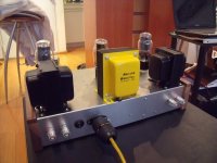
It does look like your choke creates a nice tight little tranny triangle from the PT above and the adjacent OPT above.
Try dismounting it and extending lines to it. Palmas might have hit the bullseye.
Mem,
It does look like your choke creates a nice tight little tranny triangle from the PT above and the adjacent OPT above.
Try dismounting it and extending lines to it. Palmas might have hit the bullseye.
Try rotating it 90º
Palmas, 20,
Thank you for the suggestions. Indeed they make sense; I might try those tomorrow or after tomorrow.
I have a sole power transformer for HV, 5Vac 5U4 filament, 6.3Vac filaments, and 2.5 Vac filaments. I felt it was a good idea when I ordered the custom built trafo. Now I know it wasn't.
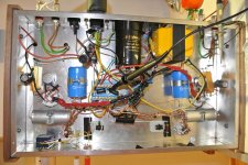
The choke is actually inside the metallic enclosure, quite near the PT which is on top the enclosure (I thought that the earthed aluminium enclosure would provide some shield for electric field). It is not directly under, I would say it's in the space inbetween the PT and OPT. The choke is rotated 90 from the PT; but it's aligned with the OPT. (See by yourselves in the attached pictures).
Today I tested attaching a spare electrolityc 100uF cap in paralell with the 100uF at the circuit and the output ripple was reduced to half the original value to 18mVrms.
I also get an answer by a person who built the amp. He built it some time ago but he remembers that the hum in his build was due to the 6SL7 stage. Anyway he changed the values of the PS power supplies in a subsequent contruction.
I'll keep you posted.
Thank you for the suggestions. Indeed they make sense; I might try those tomorrow or after tomorrow.
I have a sole power transformer for HV, 5Vac 5U4 filament, 6.3Vac filaments, and 2.5 Vac filaments. I felt it was a good idea when I ordered the custom built trafo. Now I know it wasn't.
The choke is actually inside the metallic enclosure, quite near the PT which is on top the enclosure (I thought that the earthed aluminium enclosure would provide some shield for electric field). It is not directly under, I would say it's in the space inbetween the PT and OPT. The choke is rotated 90 from the PT; but it's aligned with the OPT. (See by yourselves in the attached pictures).
Today I tested attaching a spare electrolityc 100uF cap in paralell with the 100uF at the circuit and the output ripple was reduced to half the original value to 18mVrms.
I also get an answer by a person who built the amp. He built it some time ago but he remembers that the hum in his build was due to the 6SL7 stage. Anyway he changed the values of the PS power supplies in a subsequent contruction.
I'll keep you posted.
Attachments
Double pi?
While I keep checking things out, I would like to try an additional LC section for my PSU filter. The original pi is 2uF; 8H; 100uF. I might add a 4H choke I have around with a 100uF or 47uF poly capacitor. I'm worried since I see a (hopefully) damped oscillation in the simulation. Any thoughts?
While I keep checking things out, I would like to try an additional LC section for my PSU filter. The original pi is 2uF; 8H; 100uF. I might add a 4H choke I have around with a 100uF or 47uF poly capacitor. I'm worried since I see a (hopefully) damped oscillation in the simulation. Any thoughts?
You've drawn only a single 2.5V heater supply in your graphic. If that is the case (both 2A3 tubes share one heater supply) you should rotate the connections on one 2A3 tube to see if that produces in-phase humm.
Furthermore there are more ways to squash the ripple with filtering. You could reduce ripple to half by using two identical chokes, one for left channel and one for right channel. The first cap after the 5Z3 has better 10uF/630V. You could extend the filtering with a 56 ohm resister and a 22uF cap per channel. Experiment until you have 20mV or less per channel. What's the sensitivity of your loudspeakers?
Furthermore there are more ways to squash the ripple with filtering. You could reduce ripple to half by using two identical chokes, one for left channel and one for right channel. The first cap after the 5Z3 has better 10uF/630V. You could extend the filtering with a 56 ohm resister and a 22uF cap per channel. Experiment until you have 20mV or less per channel. What's the sensitivity of your loudspeakers?
Thanks for the suggestion. Indeed 10uF instead of 2uF would be much better after the 5U4G (in my case), however that would make the HT much higher. I have a pair of 95dB/W/1m speakers. You mean a 56 ohm in series and a 22uF to ground per channel? Thank you.You've drawn only a single 2.5V heater supply in your graphic. If that is the case (both 2A3 tubes share one heater supply) you should rotate the connections on one 2A3 tube to see if that produces in-phase humm.
Furthermore there are more ways to squash the ripple with filtering. You could reduce ripple to half by using two identical chokes, one for left channel and one for right channel. The first cap after the 5Z3 has better 10uF/630V. You could extend the filtering with a 56 ohm resister and a 22uF cap per channel. Experiment until you have 20mV or less per channel. What's the sensitivity of your loudspeakers?
While I keep checking things out, I would like to try an additional LC section for my PSU filter. The original pi is 2uF; 8H; 100uF. I might add a 4H choke I have around with a 100uF or 47uF poly capacitor. I'm worried since I see a (hopefully) damped oscillation in the simulation. Any thoughts?
When you run the simulation look at the result after maybe 15 seconds. Oscilation is caused many time by the transient at turn on. Should be gone after a short while. Also did you put in the DCR of the chokes in the symulation and the ESR of the caps. These resistances will damp the PS.
One other thing to do if you see oscillation is to place a small cap and resistor in series and place this across the pouwer supply. This will damp any oscillation. But wait and measure it first because you need to select the RC constant to match oscilation freq.
That said if the pi filter is 2uf - 8H 100uf you'd gain the most bang per buck by spending about $5 and replacing that 2uF cap with at least a 20uf cap. This will reduce ripple by a factor of ten. If this raises the voltage to much then add another CRC filer section with the "R" sized to burn up some volts. You could of course replace the "R" with a choke of the same DCR and power rating but resistors cost 50 cents and use less space.
A choke is not normally cost and space effective in the second stage of a filter but they do work. Today caps give better performance per dollar.
Thanks for the suggestion. Indeed 10uF instead of 2uF would be much better after the 5U4G (in my case), however that would make the HT much higher. I have a pair of 95dB/W/1m speakers. You mean a 56 ohm in series and a 22uF to ground per channel? Thank you.
The goal is 330V at 120mA, wasn't it?
With this setup (still open for improvement) you'll have 32mV ripple.
On 95dB speakers just quiet enough, else it could be bettered by raising capacitance slightly.
An externally hosted image should be here but it was not working when we last tested it.
Seriously, are your filaments heated by a common winding? Why would you do that?
AC-heating a DHT leaves always a residue (humm) which will be noticed on 95dB speakers.
Only remedy is a dedicated DHT supply; do a quick search on this forum, there's lots of good information available.
Last edited:
Thank you for the sim run. Yes, I have only one winding for both heaters. This is my first exprience with valves and at the time I ordered the custom built transformer it just felt like a good idea. Now I know it's not. Anyway most of the noise comes from the B+, nevertheless I'm thinking about building (or buying, but they´re costly) a DC power supply for the 2A3 heaters. Thank you again.The goal is 330V at 120mA, wasn't it?
With this setup (still open for improvement) you'll have 32mV ripple.
On 95dB speakers just quiet enough, else it could be bettered by raising capacitance slightly.
An externally hosted image should be here but it was not working when we last tested it.
Seriously, are your filaments heated by a common winding? Why would you do that?
AC-heating a DHT leaves always a residue (humm) which will be noticed on 95dB speakers.
Only remedy is a dedicated DHT supply; do a quick search on this forum, there's lots of good information available.
- Status
- This old topic is closed. If you want to reopen this topic, contact a moderator using the "Report Post" button.
- Home
- Amplifiers
- Tubes / Valves
- SOS: First Build, Lots of Hum