Hello everybody.
I've just finished the construction of a 2A3 SET wit a SRPP 6SL7 gain stage. It's the Angela SRPP 2A3 (2A3 Tube Amplifier Construction Project).
I'm getting 40mVrms of hum at the speaker terminals, mainly 100Hz (mains freq is 50Hz), clearly audible even with low efficiency speakers. I've read a number af threads pointing to AC heaters. My amp has hum pots which are fully adjusted to one end to produce the less hum. The Power Supply (5UA4g) measures 1,4Vpp of ripple at B+ (measured at 288V instead of the 322 V of theoretical value, need to understand why).
For now I'm wondering how much of the 1.4Vpp ripple at B+ translates to the 40mVrms hum at the output.
Your comments will be greatly appreciated.
Thank you for your answer LinuksGuru. I rushed in the end and the build, as you see, got quite messy. I tried to twist the heather wiring though.
By the way, I made a mistake in my previous post. The B+ ripple is 2.24Vpp, twice the value at the simulations with PSUD II.
By the way, I made a mistake in my previous post. The B+ ripple is 2.24Vpp, twice the value at the simulations with PSUD II.
An externally hosted image should be here but it was not working when we last tested it.
check to see how much current you are drawing from the supply, and as a whole, compare that to the size of ur power xfrmr and see if perhaps you are drawing more than the iron can supply?
also your link is NG. if you want to post pix, best to use the "Go Advanced" or "Post Reply" and then use the upload feature of the attachment manager...
_-_-bear
also your link is NG. if you want to post pix, best to use the "Go Advanced" or "Post Reply" and then use the upload feature of the attachment manager...
_-_-bear
Hello everybody.
I've just finished the construction of a 2A3 SET wit a SRPP 6SL7 gain stage. It's the Angela SRPP 2A3 (2A3 Tube Amplifier Construction Project).
I'm getting 40mVrms of hum at the speaker terminals, mainly 100Hz (mains freq is 50Hz), clearly audible even with low efficiency speakers. I've read a number af threads pointing to AC heaters. My amp has hum pots which are fully adjusted to one end to produce the less hum. The Power Supply (5UA4g) measures 1,4Vpp of ripple at B+ (measured at 288V instead of the 322 V of theoretical value, need to understand why).
For now I'm wondering how much of the 1.4Vpp ripple at B+ translates to the 40mVrms hum at the output.
Your comments will be greatly appreciated.
If the hum is 120Hz it may not be from the heaters. Well it might be because that 6.3VAC will have lots of 120Hz on it.
The test to see if the hum is comoing from the B+ or the heaters is to get some batteries. AA cells will do and build a battery powered heater supply. It only has to run for 30 seconds, so as I said even AA cells will work. Four in series can supply an amp of 6V.
If the amp still hums with batteries on the heater then the hum id caused by the B+ poower supply. if the batteries fix the hum problem then you need to work on the heaters by
1) remove the ground connection from the hum balance pot and conect it to something that is at about 30V above ground (like a voltage divider) this "elevates" the heaters and work most of the time.
2) re wire the heater so as to eliminate "loops" in the wire. Go over the tube sockets, twist the wires 8 turns per inch (use a drill motor)
3) any signal in the amp that feeds a high impedance (like a tube grid) needs to go in a shielded cable with ONE (and only one) end of the shield tried to ground. Even so make sure no signal wire runs parallel to an AC wire
Lot of things to do but first use the battery test to determine the cause of the hum
Hi!
The AC heaters are very unlikely the cause for that kind of hum.
Are the heaters referenced to ground as indicated in the schematic? A symmetric reference to ground would be better via two resistors.
Are you using a metal chassis? Is the chassis connected to ground? Connected to safety earth?
Check all these things first then:
Disconnect the amp from any source and short the inputs. Still humming?
If so, short the output tube grid to ground and see if it still hums.
Once you've done that, the results will give hints as to where to search further
Best regards
Thomas
Hi!
Check all these things first then:
Disconnect the amp from any source and short the inputs. Still humming?
If so, short the output tube grid to ground and see if it still hums.
Once you've done that, the results will give hints as to where to search further
Thomas is 100% right. Do this and post result, at least we could hunt down most likely source of hum.
Lots of room for improvement
Thank you gentlemen for your valuable answers.
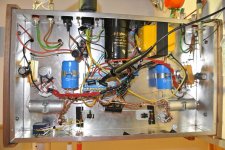
I'm attaching a hi res pic. I know it's not a clean build; I rushed thing at the end. I should replace specially the heater wiring for the 2A3s (red twisted cable). Will do that possibly today.
The enclosure is metallic, and it's connected to safety earth. Power supply 0V is also connected to safety earth. I know I could use some sort of ground loop switch but I wanted to keep it simple at the beggining. The OPT secondary is not referenced to earth. Should I do that?
Regarding grounding the grid of the 2A3 to ground, I'm wondering whether this could damage the 6SL7 by drawing too much AC current from there through the coupling cap. I prefer to sound silly by asking than to damage the 6SL7s or the caps: Should I remove the 6SL7s to make things safer?
ChrisA: As for elevating the 2A3 heater, please note that the hum pot is actually connected to the leg going to the RC auto-bias circuit so it actually gets around 40 Volts in there if I'm getting you right.
Thank you gentlemen for your valuable answers.
I'm attaching a hi res pic. I know it's not a clean build; I rushed thing at the end. I should replace specially the heater wiring for the 2A3s (red twisted cable). Will do that possibly today.
The enclosure is metallic, and it's connected to safety earth. Power supply 0V is also connected to safety earth. I know I could use some sort of ground loop switch but I wanted to keep it simple at the beggining. The OPT secondary is not referenced to earth. Should I do that?
Regarding grounding the grid of the 2A3 to ground, I'm wondering whether this could damage the 6SL7 by drawing too much AC current from there through the coupling cap. I prefer to sound silly by asking than to damage the 6SL7s or the caps: Should I remove the 6SL7s to make things safer?
ChrisA: As for elevating the 2A3 heater, please note that the hum pot is actually connected to the leg going to the RC auto-bias circuit so it actually gets around 40 Volts in there if I'm getting you right.
Hi!
There is no pic in your post...
It is difficult to help if you do not give all the information.
Is the 6SL7 heater referenced to ground as per the schematic? This is something which is easily forgotten.
Does the amp hum without any source connected and the inputs shorted?
You can short the 2A3 grid without damage, just keep the input shorted, there will be no AC signal. If you are worried, remove the 6SL7
Thomas
Elusive Attach
I'm sorry I failed to attach my picture before. I hope you can see it this time.
The 6SL7 heaters are elevated to 80Vdc so as to not exceed the maximun cathode to heater voltage. I'll check this again to be sure.
I've shorted the inputs and the hum it's still there. The FFT function at the scope shows a 50Hz and 100Hz component. The 100Hz component is twice the 50Hz one.
next step will be to ground the grids.
Thank you.
Attachments
Update: The hum it's still there even with the 2A3 grid shorted to ground. Evidence points to B+ and/or heaters. Next step should be getting a D cell holder and a 0.2 ohm resistor to power the heater. Hints on how to check the transformer current will be appreciated, taking into account that the current waveform should look like short bursts of current. The transformer was custom built according to my requirements, which I stated only to be a 150mA current draw. According to simulation, the transformer short bursts go up to 320mA each semicycle; with a rms value of around 200mA. I does not get hot but it could be saturating he core, any clues on how to look for evidence for that effect?
Hi!
Normally AC heaters on 2A3s should be adjustable via the hum pot to negligible levels.
I suspect B+ ripple or the power transformer straying into output transformers.
Is the hum still there with the 2A3 unplugged? Then you need to orientate the power transformer 90 degrees to the OPTs. You can also increase the last filter cap to see if the hum comes form the B+ ripple. Doubling the cap after the choke should reduce the hum about half.
Thomas
My amp has hum pots which are fully adjusted to one end to produce the less hum. The Power Supply (5UA4g) measures 1,4Vpp of ripple at B+ (measured at 288V instead of the 322 V of theoretical value, need to understand why).
For now I'm wondering how much of the 1.4Vpp ripple at B+ translates to the 40mVrms hum at the output.
Most (maybe 75-80%) of the B+ ripple will appear across the output transformer primary, and will be stepped down by the turns ratio of about 25, so your numbers appear about as you'd expect. That's too much ripple for a single-ended amp.
Do I read you correctly that the hum pot needs to be all the way in one direction for minimum hum? That's not great news; hopefully better after changes to the wiring dress.
All good fortune,
Chris
Re:
Thank you for your thoughts.
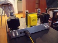
VinylSailor, as you can see, the OPTs are already installed 90 degrees respect to the Power Transformer. I've measured that and didn't get any noticeable effect on noise levels on the OPT primary winding when switching on the Power with no rectifier valve (then no HT).
Chris, you read well: minimum hum is reached in both channels with the hum pots turned all the way to a side. The ripple level on B+ is actually 2.24Vpp, twice the values at the simulations (I made a mistake when posting 1.4Vpp). I have no experience on this, but it looks pretty much to me. I already used a 100uF cap instead of the 47uF at the original schematic. Any clues on why I'm getting twice the ripple?
Thanks
Thank you for your thoughts.
VinylSailor, as you can see, the OPTs are already installed 90 degrees respect to the Power Transformer. I've measured that and didn't get any noticeable effect on noise levels on the OPT primary winding when switching on the Power with no rectifier valve (then no HT).
Chris, you read well: minimum hum is reached in both channels with the hum pots turned all the way to a side. The ripple level on B+ is actually 2.24Vpp, twice the values at the simulations (I made a mistake when posting 1.4Vpp). I have no experience on this, but it looks pretty much to me. I already used a 100uF cap instead of the 47uF at the original schematic. Any clues on why I'm getting twice the ripple?
Thanks
Attachments
The OPT secondary is not referenced to earth. Should I do that?
Yes! To do otherwise is very dangerous. (High voltage on the primary can leak across insulation, or an insulation failure can put high voltage on speaker wiring).
Chris
minimum hum is reached in both channels with the hum pots turned all the way to a side. The ripple level on B+ is actually 2.24Vpp, twice the values at the simulations (I made a mistake when posting 1.4Vpp). I have no experience on this, but it looks pretty much to me. I already used a 100uF cap instead of the 47uF at the original schematic. Any clues on why I'm getting twice the ripple?
You may be getting some inductive coupling from the power transformer to the power supply choke, but I'd guess that a couple of volts is just about what to expect from a CLC filtered supply. You can add an additional LC without too much trouble and remove that issue.
Maybe the filament hum imbalance issue is related - maybe the adjustment to one end of the pot gives an audible minimum of power supply artifacts plus line frequency hum. Well, it's a theory...
All good fortune,
Chris
That whole PS filtering looks odd with the 2 (according to the diagram) 1mf 630v input caps. (paralleled?) That huge choke can allow you to use more input filtering. You could get by with a common 500v 30/20/20 multicap system with that huge choke. What's the DCR of the PT HV secondary?
Hi!
I agree with Chris about B+ ripple, after all these tests, it's quite obvious thats the source of the hum. You need to increase filtering. The reason you need to turn the hum pots all the way to one side is: This gives some hum cancellation between B+ induced and filament hum
Thomas
I agree with Chris about B+ ripple, after all these tests, it's quite obvious thats the source of the hum. You need to increase filtering. The reason you need to turn the hum pots all the way to one side is: This gives some hum cancellation between B+ induced and filament hum
Thomas
That whole PS filtering looks odd with the 2 (according to the diagram) 1mf 630v input caps. (paralleled?) That huge choke can allow you to use more input filtering. You could get by with a common 500v 30/20/20 multicap system with that huge choke. What's the DCR of the PT HV secondary?
Oh, I didn't look far enough down the page. If that's the power supply in use, it definitely needs another LC section. That supply is basically a choke-input supply that's been trimmed up slightly with the very small input caps, and *no* additional filtering. Single-ended amps need very good filtering.
Thanks,
Chris
I'm sorry I failed to attach my picture before. I hope you can see it this time.
The 6SL7 heaters are elevated to 80Vdc so as to not exceed the maximun cathode to heater voltage. I'll check this again to be sure.
I've shorted the inputs and the hum it's still there. The FFT function at the scope shows a 50Hz and 100Hz component. The 100Hz component is twice the 50Hz one.
next step will be to ground the grids.
Thank you.
Try an FFT of the 6.3V heater supply. I bet it has some 100Hz on it. It shares an iron core with the B+ supply with has current spikes at 100Hz.
The simple test is to use a 6.3 DC supply for a few minutes and see if the hum goes away.
- Status
- This old topic is closed. If you want to reopen this topic, contact a moderator using the "Report Post" button.
- Home
- Amplifiers
- Tubes / Valves
- SOS: First Build, Lots of Hum