just noticed R602 is 82Ω instead of 180Ω doh
and R607
hope I'm not confusing people to much
rgds
jms
It's interesting seeing it was used in other models such as the TAN series.
Right just been through that check sheet I posted above, comparing that to what's actually on my PCB. Not as bad as I thought and mostly UK values - whew! The ony queries I have are with the following values:
R601/602/603 - the original resistors were literally crumbled, so I could not read any of their values. Shall I install UK circuit values here?
R604 - marked as 100R on the diagram, but a 190R is fitted.
R607 - marked as 56K, but 100K fitted (however have discussed this one a few pages back, so shall leave it as-is).
R611 - marked as 270R on UK and US circuits. 470R is fitted!
Apart from these everything is fine and checks out! Any suggestions what to do with these values?
Mucho thanks!
- John
I didn't see this post... must have appeared when I was typing.
R604... 190? or 180? Not being picky
") "190" isn't a preferred value. If it measures 190 then I suspect it's a 180 gone high, replace. Or just a typo
"190" isn't a preferred value. If it measures 190 then I suspect it's a 180 gone high, replace. Or just a typo R611 is shown as 470ohm in first picture in post #134 and in the multi voltage variant so I think that should be left at 470 ohms.
I have to keep opening this thread in more than one tab to keep referring back to all the different parts so hope I haven't made any daft mistakes in trying to carry and remember all the component numbers and values.
I looked at your photos in post #1. R604 was original then. You can tell by the soldering on the PCB.
JMS: Thanks for that schematic - still interesting to see the basic same PSU used in another Sony amp. And as for confusing people I think I've been doing that with all my updates today hahaha!
Mooly: R604 - it's listed as 180R in the service manual, but I (wrongly) thought it was 190R in practice as the resistor looked brown-white-brown-gold to my eyes. Difficult to tell the exact colours on this resistor and they may have changed with use over 30+ years, but it does indeed measure 180R, so I guess they really are brown-grey-brown-gold instead.
Another mystery solved
R611 - Ahaaa you're quite right it is shown in the UK schematic as 470R - it's listed in the components guide at the back of the manual as 270R however, hence my confusion. Another one to tick off the list then
Must take this opportunity to say thanks once again for all your help (and indeed everyone else who has posted) - this project would have been dead in the water otherwise. Sorry it's been a bit confusing with all the different scans and wot-not (I think I've gone a tad overboard with the updates on this one haha!).
- J
Last edited:
Today's update : All caps replaced with low ESR 105C types from Rubycon and Panasonic. All resistors checked and are OK, apart from R601-3 (mentioned earlier). Replacements on order so I hope they'll be arriving this week. The 5W 0.22R (R622) however was replaced just to be on the safe side.
Have decided to not use the Sony A911 for Q603 (though it passed simple multimeter diode tests) following Mooly's comments earlier, and will use an MJE350 here.
Q602 replaced with same type NOS replacement.
Once those 3 resistors & one transistor arrive and are fitted it's onto the testing stage at last
Hopefully next week will enter the home stretch!
- John
Last edited:
Will do - I'll check three times and solder once
Mooly would you know what a suitable (given the design of this amp, rather than the 'best' part on paper, as it were) replacement is for the original output transistors in this amp? They were Hitachi 2SB655 & 2SD675s. The amp actually has On Semi MJ21193 & MJ21194 fitted. Is it OK to leave these in or can I do better here? I'd like to get the originals but they're pretty much unobtainium, and the ones on Ebay all look a bit suspect to me.
Thanks,
- John
The MJ21193/4 are excellent transistors, so stick with those. You don't want to start subbing in modern parts with high fT because it will become unstable. The originals will be long obsolete and yeah, eBay ones will undoubtedly be remarked 2955/3055 fakes.
Hmm, Q603, should be OK with MJE350. You will have to bend the pins as the MJE350 is ECB and the 2SA911 is EBC. There is probably a TO-92 device that would suit, but go with it..
Hmm, Q603, should be OK with MJE350. You will have to bend the pins as the MJE350 is ECB and the 2SA911 is EBC. There is probably a TO-92 device that would suit, but go with it..
Last edited:
Sounds like the main amp has been worked on too. As above with the MJ21193/4, they should be fine.
Have you measured these ? Are they OK.
What I was wondering is whether you have a spare ? mains transformer from any other amps that we could rig up too test the main amp is OK.
Any tranny capable of generating rails in the 30 to 50 volt range should be good to test. Even a 0.5 to 1 amp tranny would do. All you would need is a bridge rectifier.
A major concern is if there is a problem in the amp itself, and that sees off the rebuilt PSU.
Just trying to cover all possibilities
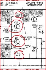
Looking at the power amp Q308 and 309 and 358 and 359 are of a "type" that was prone to failing open circuit intermitently. That's a bit unscientific as a statement, but I have seen it many times in various gear... Hitachi devices in that package failing.
Have you measured these ? Are they OK.
What I was wondering is whether you have a spare ? mains transformer from any other amps that we could rig up too test the main amp is OK.
Any tranny capable of generating rails in the 30 to 50 volt range should be good to test. Even a 0.5 to 1 amp tranny would do. All you would need is a bridge rectifier.
A major concern is if there is a problem in the amp itself, and that sees off the rebuilt PSU.
Just trying to cover all possibilities
Looking at the power amp Q308 and 309 and 358 and 359 are of a "type" that was prone to failing open circuit intermitently. That's a bit unscientific as a statement, but I have seen it many times in various gear... Hitachi devices in that package failing.
Thanks Jaycee - I'll keep those ones in then assuming they weren't taken out by the surge when the amp blew.
Mooly - Wow this is starting to get more complex by the minute haha! I do have a 300VA 35-0-35 transformer I could use and have a 10A bridge rectifier. Suitable? I'm hoping this amp hasn't already been worked on by the previous (two) repairers as far as replacing items on the power-amp board are concerned... or else it probably isn't a TA-F6N now really I guess. I recall the board looks pretty much stock going by the dust and general patina of the components, but if the outputs were changed I guess those Qs you mentioned may have been changed too.
I need to concentrate on one thing at a time though - I'll get this PSU sorted first, then test the main amp. Assume it's fairly simple to rig up that transformer/bridge rectifier and splice it into the power-amp?
Thanks!
- John
That tranny sounds just the job... and again use with a 60 or 100 watt bulb in series.
Yes two minutes work to rig up and test, and well worth doing. All the (simple) wiring and bridge is done on the tranny with just three wires feeding off to the amp.
Haven't looked it up but I don't think OnSemi even existed when this was made, and certainly not the MJ devices. Sony always used Jap parts in those days.
Cool - as the chassis forms the earth (as discussed a few pages back I think) would I have to attach anything to that (the CT?) to ensure safe operation? I'll sketch it out later as I prefer to work with a visual aid and know what I'm doing before-hand.
Yes the Sony used Hitachi 2SB655 & 2SD675s outputs. Those On Semi's were fitted by the repair man, the same one who left the switching transistor clamp off the SMPS, and used a mixture of switching transistors which probably created an imbalance/oscillation as they're all different hFE's. He only replaced a couple of capacitors too when they all needed replacing. I'm hoping nothing else has been bodged after all this effort (and money).....
Yes the Sony used Hitachi 2SB655 & 2SD675s outputs. Those On Semi's were fitted by the repair man, the same one who left the switching transistor clamp off the SMPS, and used a mixture of switching transistors which probably created an imbalance/oscillation as they're all different hFE's. He only replaced a couple of capacitors too when they all needed replacing. I'm hoping nothing else has been bodged after all this effort (and money).....
Just checked the main power-amp board, and Q308 and 309 and 358 and 359 are indeed the originals. Nothing else appears to have been changed either, so I guess the original repairer just replaced the output power transistors to be on the safe side, or because they looked corroded perhaps (on all photos on the net I have seen of the outputs, the transistor casing always looks oxidised so one could perhaps be fooled into thinking they'd gone bad or something), or because he was perhaps shooting in the dark. I'm actually relieved nothing has been tampered with on the main board, judging by the state of the SMPS!
Going to replace all the caps in the PSU board now - amazing how caps have decreased in size over 30 years. The new 1000uF 200V caps are a third of the height of the hulking big Nichicon originals! Going to replace the two 220k resistors (R806/807) too with precisely matched 2W metal oxide jobs just to play it safe, though will have to mount those underneath the board (plenty of space/air here) for them to fit. They don't appear to dissipate any heat. I've also ordered a new 14W 150R wirewound to replace R804 - the original is probably thermally stressed after 30+ years of heat. Ditto the two 2.2uF 100V caps (C806/807) as the case on one (next to the power resistor) has blackened over the years. I'll mount the new ones underneath too so they're not subject to the heat from that wirewound.
- John
Going to replace all the caps in the PSU board now - amazing how caps have decreased in size over 30 years. The new 1000uF 200V caps are a third of the height of the hulking big Nichicon originals!
Going to replace the two 220k resistors (R806/807) too with precisely matched 2W metal oxide jobs just to play it safe, though will have to mount those underneath the board (plenty of space/air here) for them to fit. They don't appear to dissipate any heat. I've also ordered a new 14W 150R wirewound to replace R804 - the original is probably thermally stressed after 30+ years of heat. Ditto the two 2.2uF 100V caps (C806/807) as the case on one (next to the power resistor) has blackened over the years. I'll mount the new ones underneath too so they're not subject to the heat from that wirewound.- John
Last edited:
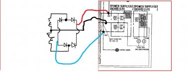
Centre tap of tranny goes to main zero volt point at junction of C802 and C803. That point if you measure it is probably connected directly to the case anyway.
Just imagine your tranny takes the place T603 in the PSU. Wired just the same, all that's different is that your bridge connects directly to C802 and C803 to provide the -/+ rails.
Just imagine your tranny takes the place T603 in the PSU. Wired just the same, all that's different is that your bridge connects directly to C802 and C803 to provide the -/+ rails.
Centre tap of tranny goes to main zero volt point at junction of C802 and C803. That point if you measure it is probably connected directly to the case anyway.
Just imagine your tranny takes the place T603 in the PSU. Wired just the same, all that's different is that your bridge connects directly to C802 and C803 to provide the -/+ rails.
Oh right as easy as that? Good news it means it's 'me proof' hahaha! That PSU board flips out of the case easily too (plenty of length on the wires) so it will be easy to solder that all together. Hope the 35-0-35 transformer has enough volts - the power-amp has a relay and I'm not sure at what voltage it kicks in and the amps starts running.
- J
Like this.
A 35 0 35 vac tranny will give around -/+50 volts... maybe a little more at low current. That's not a problem as the 60 watt bulb will pull that down a little.
The original PSU is disconnected... none of it is used. Doesn't matter if the voltage ended up to low to pull the speaker relay in (it won't) as it still lets us do a couple of quick measurements to prove the amp is OK.
A 35 0 35 vac tranny will give around -/+50 volts... maybe a little more at low current. That's not a problem as the 60 watt bulb will pull that down a little.
The original PSU is disconnected... none of it is used. Doesn't matter if the voltage ended up to low to pull the speaker relay in (it won't
) as it still lets us do a couple of quick measurements to prove the amp is OK.Attachments
Ah thanks (yet again!) Mooly - yes that's all clear.
Regarding the lightbulb I assume that's the same deal as before i.e. replacing the fuse (connected to the transformer) with wires from each end of the fuse holder to the bulb holder?
The transformer is inside a clone I made of a Naim NAP140. I assume I can just unclip the PSU spade connector wires from off the output side of the Naims PSU board, and instead clip on some wires which lead from there to the Sonys PSU board (as you kindly drew out). I'm guessing the extra capacitance from jumping off of the Naims PSU board won't metter, as it's just effectively adding capacitance to C802/803?
On the underside of the Sonys PSU board it's all labelled nicely. I did a continuity check between G and the chassis, and it predictably beeped. However on the B- it beeped too. And - should I be worried here - it beeped for only a second between B+ and the chassis. Each time I repeat that one it beeps for just a second then is silent. For the G and B- it's a continuous beep from the multimeter on continuity setting.
- John
Last edited:
The beeb is just the meter reading via all the circuitry between the rails... it's the "ohmage" or lack of that matters If zero line is connected to chassis it will be essentially zero.
The PSU you have sounds good to use, no problem taking already smoothed DC and putting it across the Sony rails.
Check on ohms what each rail reads to ground... and although that's not a good way to advise detailed testing it will show if there is a dead short. So check that rail that beebs all the time... measure the resistance.
Are you sure all four output devices are OK (none short circuit) ? and also the four 0.22 ohms are OK
If the 0.22 ohms are OK then you can read from collector (the case of each output transistor) to each rail to see if any device is short circuit.
Using a bulb and nothing will pop even there is a short so don't worry, but it makes sense to check as much as possible first.
If zero line is connected to chassis it will be essentially zero. The PSU you have sounds good to use, no problem taking already smoothed DC and putting it across the Sony rails.
Check on ohms what each rail reads to ground... and although that's not a good way to advise detailed testing it will show if there is a dead short. So check that rail that beebs all the time... measure the resistance.
Are you sure all four output devices are OK (none short circuit) ? and also the four 0.22 ohms are OK
If the 0.22 ohms are OK then you can read from collector (the case of each output transistor) to each rail to see if any device is short circuit.
Using a bulb and nothing will pop even there is a short so don't worry, but it makes sense to check as much as possible first.
Attachments
Damn memory - just had a look at that transformer and it's actually 25-0-25 - that's not high enough is it
I guess I can still do the other tests you mention above on the continuity setting however which is better than no test at all.
Regarding the other tests on the Sony PSU board, G to chassis = 00.5ohms. B+ and B- to chassis are both completely null.
- John
I guess I can still do the other tests you mention above on the continuity setting however which is better than no test at all.
Regarding the other tests on the Sony PSU board, G to chassis = 00.5ohms. B+ and B- to chassis are both completely null.
- John
Last edited:
Hmmm readings on continuity/low ohms setting from the cases of all four On Semi output transistors to each rail on the PSU PCB are completely null. Bad news?
As for measuring the 0.22 resistors it's impossible to get the probes in there as it's tightly packed. I really don't want to remove the heatsinks and the power-amp PCB either as it involves quite a bit of desoldering and shifting around of bits and it's getting a little beyond my DIY experience threshold I'm afraid.
As for measuring the 0.22 resistors it's impossible to get the probes in there as it's tightly packed. I really don't want to remove the heatsinks and the power-amp PCB either as it involves quite a bit of desoldering and shifting around of bits and it's getting a little beyond my DIY experience threshold I'm afraid.
- Home
- Amplifiers
- Solid State
- Sony TA-F6B PSU repair