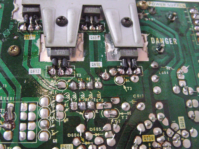
How it looked originally, minus the missing transistor clamp which I'll be creating this week:
And a shot from someone else's amp with the clamp in place:
An externally hosted image should be here but it was not working when we last tested it.
And a shot from someone else's amp with the clamp in place:
Last edited:
Have a look at these,
BERGQUIST|3223-07FR-104NH|THERMAL PAD, TO-3P | Farnell United Kingdom
You really need them without the hole (like these) and TO3P are larger than T0220
BERGQUIST|3223-07FR-104NH|THERMAL PAD, TO-3P | Farnell United Kingdom
You really need them without the hole (like these) and TO3P are larger than T0220
Now i see. The silver pads under the transistors are metal inserts. What an odd way of doing it. TO-3P pads definitely big enough i reckon.
It's typical of the era... allows the transistors to fit flush with the pcb rather than having to preform the legs to inset them to touch the heatsink. Cost and weird ways of doing things was no object back then. All wonderfully screwed together gear.
"Have a look at these,
BERGQUIST|3223-07FR-104NH|THERMAL PAD, TO-3P | Farnell United Kingdom "
Thanks for that link Mooly - they look just the ticket!
Unfortunately the minimum order is annoyingly £20 on Farnell when paying by card and I maxed out my spending this month on the transistors/capacitors for this project on my last Farnell order.
I don't suppose anyone could piggyback 4 of these pads onto their next order? Cheeky request I know! These minimum order rules are a PITA!
- John
EDIT: They appear to do them here too - I'll look into their minimum order pricing:
http://www.rapidonline.com/Electron...w/38-1068?source=googleps&utm_source=googleps
Last edited:
Managed to order via Rapid without any tedious joining up screens to fill in. £12 for 4 pads & delivery... expensive but not as bad as RS or Farnell.
Rapid Electronics - Electronic Components
Rapid Electronics - Electronic Components
Haha damn if I'd known about that sheet I'd have got that instead (better value for money). Ah well too late now. Ordered the T0-P3s so hope they'll be fine. Might be a bit fiddly to place as they're not adhesive, and - unlike the original large silpad - there won't be any parts that protrude through the pads from the die-cast block which helped to keep the original in place until everything was screwed down.
- J
- J
Maybe a tiny dab of something just to tack it... pin head sized... even heatsink compound. Wouldn't use most glues as it would be too uneven.
I sent the pads back to Rapid Electronics in the end and instead ordered that 12" x 12" sheet which (I hope) will be arriving tomorrow. Thought I'd best stick with the same size/shape insulating pad as the original (which I'll use as a template) plus its easier to handle/position.
This pesky illess had meant I haven't done anything at all to the amp this week, but I'm hoping I'll be able to make more progress again over the weekend.
- John
Me too - and I hope it's not a charred PCB and me with a sooty face and sudden afro  Hahaha!
The 12" x 12" Sil-pad sheet arrived today. New insulator cut out and fitted between the PCB/die-cast block assembley, as well as a smaller one fitted on the side of the unit, which fits underneath Q601 & Q613. Tomorrow just got to test a few remaining resistors then going to solder in all the new components, bar those 4 switching transistors on the underneath.
- John
Hahaha!The 12" x 12" Sil-pad sheet arrived today. New insulator cut out and fitted between the PCB/die-cast block assembley, as well as a smaller one fitted on the side of the unit, which fits underneath Q601 & Q613. Tomorrow just got to test a few remaining resistors then going to solder in all the new components, bar those 4 switching transistors on the underneath.
- John
OK. Just been checking resistors - glad I did as R601, R602 and R603 were all blown in half! (not visible to the naked eye as they were covered in some kind of heat-proof fabric. Sliding the fabric off the resistors were just crumbled inside! No big problem however they can be replaced.
What IS annoying is I then measured R604. This measured 180-ohms. According to the service manual it SHOULD be 100-ohms for the UK model, with 180 being for the US model!!! Arghhhhhh!
I'm starting to think that either Sony started fitting US PSUs to all TA-F6B amps, or the 'repair' man got a replacement without checking what country it was for...
I really am stumped now & am not sure how to proceed! Continue replacing 'like with like' according to what was actually on the PCB (bearing in mind this amp has gone wrong twice), or choose to stick to the UK schematic and go through component by component checking to see - and replacing if so - any components that have the US values instead of the UK? To be fair this probably won't take too long as it appears to be just resistors which change between PCBs.
I'm going to go through and make a list of every resistor and cap on the PSU. I'll then go through and note changes to the US/UK versions and then compare with what I have on my PSU. I'm betting when there's a choice it'll be the US version each time...
I'm not surprised this amp blew its transistors if it was using US PCB values on the UK supply!
Frustrating
- John
Last edited:
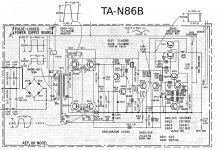
Just incase anybody finds them helpful, here are the UK and US/Canadian diagrams for the SMPS in the Sony.
UK:
US/Canada:
It appears mine (and others I have seen pictures of online) has the proper UK choke, line filter & transformers, and caps, and yet the majority of the resistor values appear to be from the US version!!! It's bizarre. I've made a list and am going to go through each component in turn noting what it currently installed on my board.
Starting to look as if Sony perhaps made a bit of a mistake, either in the service manual, or on the UK/Euro model boards (perhaps explaining why so many people always have problems with the SMPS on this model maybe, rather than it just being an old caps issue)... to be continued!
- John
UK:
An externally hosted image should be here but it was not working when we last tested it.
US/Canada:
An externally hosted image should be here but it was not working when we last tested it.
It appears mine (and others I have seen pictures of online) has the proper UK choke, line filter & transformers, and caps, and yet the majority of the resistor values appear to be from the US version!!! It's bizarre. I've made a list and am going to go through each component in turn noting what it currently installed on my board.
Starting to look as if Sony perhaps made a bit of a mistake, either in the service manual, or on the UK/Euro model boards (perhaps explaining why so many people always have problems with the SMPS on this model maybe, rather than it just being an old caps issue)... to be continued!
- John
Last edited:
I also made a PDF containing a list of components and the differences (according to the service manual!) between UK and US versions (any caps/resistors not mentioned are the same between both):
http://rapidshare.com/files/445178803/Sony_TA-F6B_resistor_regional_differences.pdf
http://rapidshare.com/files/445178803/Sony_TA-F6B_resistor_regional_differences.pdf
Right just been through that check sheet I posted above, comparing that to what's actually on my PCB. Not as bad as I thought and mostly UK values - whew! The ony queries I have are with the following values:
R601/602/603 - the original resistors were literally crumbled, so I could not read any of their values. Shall I install UK circuit values here?
R604 - marked as 100R on the diagram, but a 190R is fitted.
R607 - marked as 56K, but 100K fitted (however have discussed this one a few pages back, so shall leave it as-is).
R611 - marked as 270R on UK and US circuits. 470R is fitted!
Apart from these everything is fine and checks out! Any suggestions what to do with these values?
Mucho thanks!
- John
Hi John,
Sounds like your having fun. In view of all those resistors being zapped it's now essential to replace Q602 and Q603... can't recall from memory whether you were planning on reusing Q603 without reading back... but don't. They all have to be replaced.
As to the resistor values... you can usually tell if a part is original. Most repair techs would not use Sony supplied parts for resistors etc. Perhaps that is easier said than done identifying them as it comes down to experience too.
The function of all these resistors is to help the transistors turn OFF quickly, and although it is a hugely critical job they perform, the actual value is "relatively" unimportant. Sony may well have standardised parts... remember the version with the switchable voltage selector has to work on both voltages. Too low a value for R604 and the resistor network connected to Q604 collector may not be sufficient to fully turn on Q603 particularly if Q603 were at the low end of the gain tolerance.
Does your have all the four 39K resistors R605, 624, 625 and 626 fitted or just the two R605 and 624 ?
How-do Mooly!
I desoldered Q602 & Q603 and tested them both. Q602 is toast, and has already been replaced with an exact duplicate (managed to get a couple of brand new old stock items still in their Sony packaging).
Q603 however checks out fine using the diode test function on my multimeter between base-emitter & base-collector (one way conducting, and nothing between collector-emitter, as it should be). I feel confident in soldering that one back in.
Yes my board has the 4 x 27K fitted so that is correct, and as per the UK diagram. The two 39Ks are only for the US variant.
For R601/2/3 I'll take a chance and install the UK values, since 90% of the values do appear to be the UK versions now I've checked it over thoroughly.
As for R604 I'll take a calculated gamble and leave that one in then - I've noticed it's that same value on all other photos on the net, so Sony must have changed the value from 100R to 180/90R at some point & it didn't make the 1978 edition of the service manual (I think my amps a 1980 version).
I'm hoping L603 (22uH inductor) is OK as that was connected to one of the fried resistors (R601). Is there an easy way to test these?
Getting there.... getting there!
Last edited:
L603 should be OK. It should read very low ohms end to end. If it failed it will be open.
For R603 to have failed means that it got zapped by excess current through either/both Q602 and Q603. You need to be very sure it's OK, more so than just a simple diode test might show. This is where the old AVO and it's high ohms range and 15 volt battery came in for testing semiconductors. It could leaky devices that a DVM said was OK.
Hopefully our testing method will confirm non destructively if it's all OK.
- Home
- Amplifiers
- Solid State
- Sony TA-F6B PSU repair