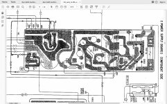
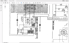
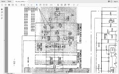
Hi Mooly, hope you still reading. Another problem arose: PSU ground has 100V potential against the ground in the wall socket. Hence connecting the input to any CD or preamp forcing auto-cutouts to switching off all power in my apartments. So I can use the amp only with ipod...
Still reading...
Is that the PSU secondary ground you are referring to (chassis). Yes of course it is If so then you need to do a leakage test of some kind. Hard to say what could be causing that. Leakage inductance in the tranny or some insulation issue with the switching transistors.
You need to do a leakage test of some sort, perhaps a 1k5 resistor paralleled with a 0.01uf cap from chassis to ground and then measure (if it will let you) the AC volt drop across the resistor. If the resistor goes up in smoke then you have a real major issue somewhere.
Not sure what to make of that really but it doesn't sound good.
Is that the PSU secondary ground you are referring to (chassis). Yes of course it is
You need to do a leakage test of some sort, perhaps a 1k5 resistor paralleled with a 0.01uf cap from chassis to ground and then measure (if it will let you) the AC volt drop across the resistor. If the resistor goes up in smoke then you have a real major issue somewhere.
Not sure what to make of that really but it doesn't sound good.
OK, will try, thanks.
issue fixed using 3-line power cord with separate ground wire (instead of native 2-line w/o ground) with ground connected to chassis directly.
I just bought one as is for parts, the PS board section was cut off, does any one have one can it be remade again?
https://www.hifido.co.jp/photo/13/047/04771/k.jpg
https://www.hifido.co.jp/photo/13/047/04771/k.jpg
There is pretty much zero chance of successfully building a supply to the original design as there are unique wound wound components involved.
Just make a normal linear supply of appropriate voltages... which tbh will be infinitely more reliable than the original self oscillating supply.
Just make a normal linear supply of appropriate voltages... which tbh will be infinitely more reliable than the original self oscillating supply.
I bought a poorly maintained F6B, but it functioned basically (thermal fuse was blown (and bypassed) and caused the relay (casing) to melt. It sounded quite amazing! But what an awful sour smell. Leaky caps?
So, I started recapping. First the PLPS and the filter caps. Bulb start, okay! A spot on 97V from the PLSP. Encouraged I took the power amplifier board out. Painstakingly careful it took the caps one by one. Cleaned the power transistor, etc. I let it rest for some days to check all caps had been replaced in order. Over and over, just to be sure.
Finally, I dared to hook it up. Bulb start, yes, I heard the second relay kick in as well. Took some time though… Than I put the power back on without the bulb. Yeah, it worked. But hold on, what’s that? The VU meters started to flicker, the MPC resistors on the power board glowed for a second. I shut it down in an instant, but oh no, the damage already had been done ☹
Ordered new resistors and start relay. Measured the power transistors and at least 1 seems to have died. After installing I tried to start it up again with the bulb. Sadly, nothing happened. The amp is totally dead.
In the end I noticed I had mounted 2 tiny caps in the opposite direction after all. F*#^ C361 and C362. Could they be the culprits? So I replaced those with new ones. Still no working amp.
So, my question is, if one of the power transistors is kaput, is it normal the whole amp does not work?
Sounds like those incorrectly fitted caps have caused the PLPS to fail. Any failed transistor in the PSU will prevent it working.
Its really bad luck but pretty much everything was covered in this thread regarding the PLPS and its possible problems. One very real issue is being able to get suitable replacement semiconductors... its now such an obsolete design.
Its really bad luck
After your advice I started measuring the PLPS. I found a faulty resistor 
The rest of the components, also the transistors seem to read fine.
Power resistors have been replaced earlier by Sanken C2023. One of the small ones Q608 also reads fine but has corroded legs. Even the solder had oxidized on the emitter connector?!
Well, very curious what will happen after replacing the resistor, have to find one first.
All, Hi. Installed the transistors that are listed as analogs, but the power supply o
All, Hi. Installed the transistors that are listed as analogs, but the power supply outputs 124 volts and does not reduce to the required 98 and 99 volts and RT601 is not regulated. What could be the problem?
All, Hi. Installed the transistors that are listed as analogs, but the power supply outputs 124 volts and does not reduce to the required 98 and 99 volts and RT601 is not regulated. What could be the problem?
- Home
- Amplifiers
- Solid State
- Sony TA-F6B PSU repair


